background image


12 

② 

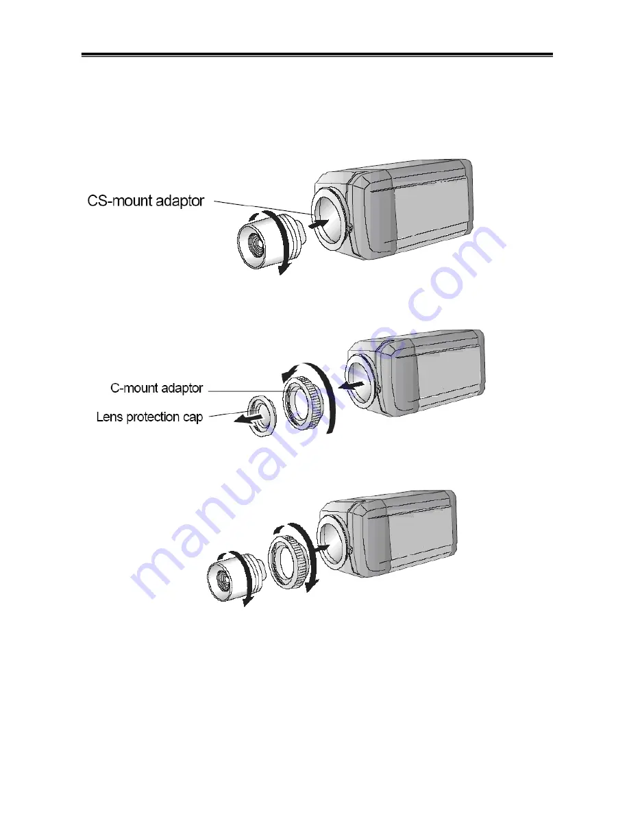
When using a CS-Mount lens


Please take off the lens protection cap and attach the CS-Mount   

lens to the camera by screwing it in clockwise. 


③ 

When using a C-Mount lens


-  Please take off the lens protection cap and attach the C-mount adaptor. 


-  Please attach the C-Mount lens to the camera by screwing it in clockwise. 

-   


Note) 

• Please use the specified lens connection parts as shown in the picture below. 

The use of the wrong sized parts may cause damage to the inside of the camera or result   

in poor fitting. 

• Use of a lens which is too heavy affects the balance of the camera and may cause a   

Summary of Contents for DCC-600F

Page 1: ...High Resolution D N WDR COLOR BOX CAMERA 560 TVL MANUAL...

Page 2: ...2...

Page 3: ...protection against harmful interference when the equipment is operated in a commercial environment This equipment generates uses and can radiate radio frequency energy and if not installed and used i...

Page 4: ...ime fire may be caused Do not Install the camera on a surface that can not support it Unless the surface is suitable it could cause falling or other hazards Do not hold plug with wet hands It could ca...

Page 5: ...5 1 Features 6 2 Components 7 3 Names and functions of parts 8 4 Installation 10 5 Setup Menu Operation 12 6 Troubleshooting 26 7 Specifications 27 Contents...

Page 6: ...ppropriate mode depending on its environment By day the camera switches to color mode in order to maintain optimal color At night it switches to B W mode so as to obtain better picture definition True...

Page 7: ...7 1 COLOR CAMERA 2 AUTO IRIS LENS CONNECTION PLUG 3 C MOUNT ADAPTOR 4 L WRENCH 5 MANUAL 2 Components...

Page 8: ...he Back Focal length Mounting bracket screw hole Please use the screw hole when fixing the camera onto the mounting bracket Please use the clamp screw as specified picture The mounting bracket can be...

Page 9: ...the camera Setting button SETUP button Used for the menu display This button can be used to confirm settings after changing the value of the selected function or current conditions UP DOWN buttons Use...

Page 10: ...clean Any foreign objects and finger marks on the lens can cause inferior image quality in low light level conditions When using an auto iris lens Please peel off about 8mm of the outer skin of the au...

Page 11: ...the lens protection cap and then attach the auto iris lens to the camera by screwing it in clockwise Please insert the connection plug that is connected to the auto iris lens cable into the auto lens...

Page 12: ...s protection cap and attach the C mount adaptor Please attach the C Mount lens to the camera by screwing it in clockwise Note Please use the specified lens connection parts as shown in the picture bel...

Page 13: ...tput terminal located on the back of the camera to the monitor The connection method varies depending on the type of monitor and accessories Please refer to the user s manual for each instrument Pleas...

Page 14: ...er to the camera Select CAMERA ID option on the CAMERA SETTING menu Use Left or right Button to select a CAMERA ID OFF 1 255 EXPOSURE Select EXPOSURE option Use Left or right button to select a mode A...

Page 15: ...cific area of picture The HSBLC mode is automatically activated only in low illuminance scene AREA SETTING Use left or right button to select a area then use left or right button to select a ON or OFF...

Page 16: ...hutter speed for camera exposure You can change the shutter speed to higher speed to capture fast moving subjects though the image becomes darker Select SHUTTER option on the EXPOSURE menu Use left or...

Page 17: ...unset When the scene is dim AWC PUSH If you select the AWC PUSH mode you will be able to set up the White Balance automatically using button MANUAL You can set the white balance options manually COLOR...

Page 18: ...r right button to select a ON and press setup button The MOTION DETECTION menu appears Use left or right button to select a zone number AREA1 AREA4 on the ZONE NUMBER option Use left or right button t...

Page 19: ...ht button to select a zone number AREA1 AREA8 on the MASK NUMBER option Use left or right button to set up the ON or OFF on the DISPLAY option Use left or right button to select the color of the mask...

Page 20: ...digital effect SHARPNESS setting Sharpness the image outline Select SHARPNESS option on the SPECIAL menu Use left or right button to change a adjust the option If you set the sharpness value to highe...

Page 21: ...e the camera identification to assign a number and character to the camera 0 9 A Z a z To disappear the user title select OFF Select USER TITLE option on the SPECIAL screen Use left or right button to...

Page 22: ...on CAMERA REBOOT Reboot the camera system FACTORY RESET Clear certain settings and information and return to factory default settings Press to confirm your selection If there are problems in operation...

Page 23: ...adjust the brightness level There is a problem with the camera operation Please check if an appropriate power source to the camera complies with the manufacturer s standard requirement or if the volta...

Page 24: ...n Off Digital Zoom X8 Digital Effect Off V Flip Mirror Rotate White Balance ATW AWC Manual BackLight BLC WDR 60dB HSBLC Wide Dynamic Range 52Db AGC Low Middle High Off 3D DNR Off Low Middle High Priva...

Page 25: ...25...

Page 26: ...26...

Reviews: