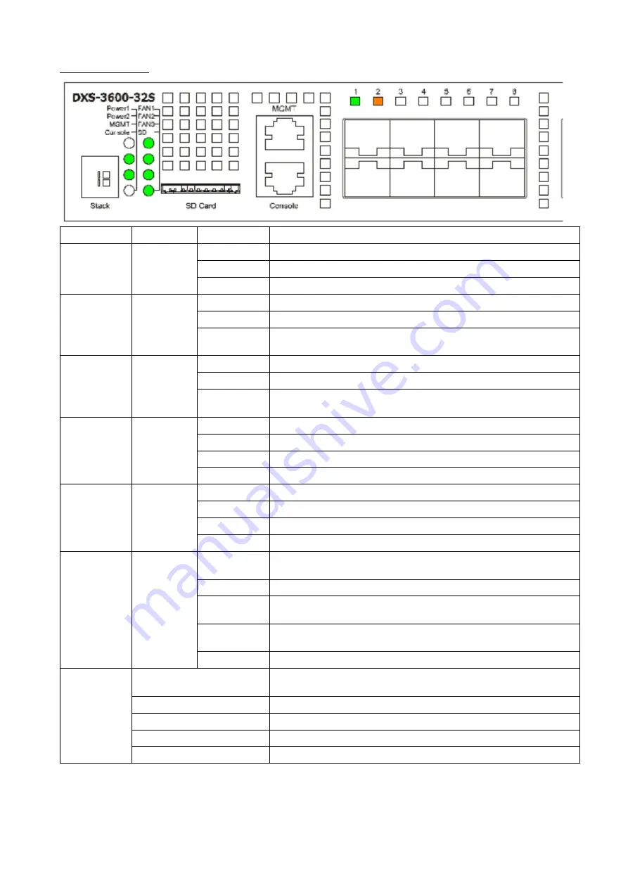
background image

LED Indicators

LED Indicative Colour

Status

Description

Power 1, 
Power 2

Green/Amber Solid Green

Power on

Solid Amber

Power supply fails

Light off

Power off

Management 
(MGMT)

Green

Solid Green

A link to the management port was successfully established

Blinking Green When activity on this port is taking place

Light off

There is no link present or when this interface was shutdown from within
the switch’s configuration

Console

Green

Blinking Green During the Power-On Self Test (POST)

Solid Green

A user is logged in through the console port

Light off

After the POST finished successfully and no user is connected to the 
console port

Fan1, Fan2, 
Fan3

Green/Amber Solid Green

When the fan is operating normally

Solid Amber

When the switch is booting up or when a diagnostics test is taking place

Blinking Amber When a fan fails

Light off

When the fan is not receiving power

SD

Green/Red

Solid Green

If a Secure Digital (SD) card is plugged in

Blinking Green When the Switch is reading or writing data to and from the SD card

Light off

When no SD card is plugged into the SD port

Solid Red

When an SD card failure has been detected

Link/Act

Green/Amber Solid Green

When there is a secure connection to a 10Gbps Ethernet device at any 
of the ports

Blinking Green When a 10Gbps port is active

Solid Amber

When there is a secure Ethernet connection to a 1Gbps Ethernet device
at any of the ports

Blinking Amber When there is reception or transmission (i.e. Activity-Act) of data

occurring at any of the ports / when a 1Gbps port is active

Light off

When there is no link or activity

Stacking ID

1-4

Indicates the stacking ID, which can be assigned manually by the user 
or automatically by the system

H

Indicates this switch is the master switch in the stack

h

Indicates this switch is the backup master switch in the stack

E

Indicates there was an error in the system’s self-test

G

Indicates the Safeguard engine entered the exhausted mode

4

Summary of Contents for DXS-3600-32S

Page 1: ...Quick Installation Guide 3 Fan AC Power Supply 1 Expansion Slot 24 Port 10GBase X SFP L3 Management Stacked Switch 3 24 10GBase X SFP 1 AC 3 DXS 3600 32S...

Page 2: ...about the device its components making network connections and technical specifications please refer to the User Manual Package Contents DXS 3600 32S Switch Power Cord AC power supply module 3 Fan mod...

Page 3: ...nt and monitoring This port uses a special console cable included with the packing with a DB9 interface to connect the Switch to a PC s COM port 10 Gigabit ports This switch is equipped with SFP SFP W...

Page 4: ...power SD Green Red Solid Green If a Secure Digital SD card is plugged in Blinking Green When the Switch is reading or writing data to and from the SD card Light off When no SD card is plugged into the...

Page 5: ...r supply tray with front to back airflow Fan Module Slots DXS 3600 FAN FB normal fan tray with front to back airflow Installation Desktop or Shelf Installation When installing the switch on a desktop...

Page 6: ...riate open space in the rack using the screws provided as seen in the figure below 3 Simply slide the switch fastened bracket B into fastened bracket C into the rack 4 Lastly fasten mounting bracket A...

Page 7: ...above When the primary AC power connection fails the secondary AC power connection will take over all the power immediately and automatically The AC power supply modules are hot swappable meaning tha...

Page 8: ...fail If both power sources fail unplug the switch When the power source has been restored plug the switch s power back in NOTE The Power Modules all support a specific airflow direction This air flow...

Page 9: ...dicate that packet activity is taking place on that port The diagram below display a typical end node connected to the Switch Switch to another Switch Another popular configuration is to connect this...

Page 10: ...s a break in the chain then data transfer will obviously be affected Duplex Ring The Duplex Ring stacks switches in a ring or circle format Each switch in a chain is connected to the upper and the low...

Page 11: ...following stacking topologies The figure below illustrates how switches can be stacked in a Duplex Chain formation using the DXS 3600 EM 4QXS module The figure below illustrates how switches can be st...

Page 12: ...ari version 4 0 and later SNMP based Management The Switch can be managed with an SNMP compatible console program The Switch supports SNMP version 1 0 version 2 0 and version 3 0 Command Line Interfac...

Page 13: ...imply connect to this Switch for the first time by pressing the Enter key After pressing Enter access will be given to enter commands after the command prompt Switch appears NOTE the first user automa...

Page 14: ...ce By default there are no user accounts configured on this Switch This will open the user authentication window as seen below Enter the login User name and Password and click OK to proceed Additional...

Page 15: ...5 c 2 6 7 A 2010 B 2011 2012 D 2013 E 2014 F 2015 G 2016 H 2017 I 2018 J 2019 1 2 9 A B DXS 3600 32S DXS 3600 32S 3 DB 9 RJ 45 4 2 19 CD...

Page 16: ...GMT Out Of Band 10 100 1000 RJ 45 DB 9 CLI 10 Gigabit SFP SFP WDM 10 DXS 3600 EM 4XT 4 10GBase T DXS 3600 EM 8T 8 1000Base T DXS 3600 EM 4QXS 4 40G QSFP DXS 3600 EM 8XS 8 10G SFP DXS 3600 EM Stack 2 1...

Page 17: ...anagement MGMT MGMT MGMT Console Power On Self Test POST Power On Self Test POST Fan1 Fan2 Fan3 SD SD SD SD SD SD Link Act 10 10 1 1 Stack 1 4 Stacking ID H master h backup master E G Safeguard engine...

Page 18: ...DXS PWR300AC 300 DXS PWR300DC 300 DXS 3600 FAN FB 19 18...

Page 19: ...1 2 3 4 SFP 19...

Page 20: ...100 240 50 60 1 18 AWG 20...

Page 21: ...2 DC 48 5 2 21...

Page 22: ...10 100 1000 RJ 45 VoIP UTP STP Link Act SFP SFP WDM QSFP DXS 3600 EM 4QXS 22...

Page 23: ...DXS 3600 32S IP Telnet Web RJ 45 SNMP DXS 3600 EM Stack DXS 3600 EM 4QXS DXS 3600 EM Stack DEM CB50CXP CXP 50 DXS 3600 EM Stack DXS 3600 EM Stack 23...

Page 24: ...DXS 3600 EM 4QXS QSFP DXS 3600 EM 4QXS DXS 3600 EM 4QXS 24...

Page 25: ...Web Web Internet Explorer 6 0 Netscape 7 0 Mozilla Firefox 3 0 Google Chrome 5 0 Safari 4 0 SNMP SNMP SNMP 1 0 2 0 3 0 CLI CLI CLI RJ 45 RS 232 Hyperterminal Putty Mimicom DB 9 RJ 45 25...

Page 26: ...d rate 115200 Data bits 8 Parity Stop bits 1 Flow control Properties VT 100 Ctrl Windows 3 console login Enter Switch Web Web IP Enter MGMT IP 192 168 0 1 24 LAN IP IP IP IP 10 90 90 90 IP 10 x y z x...

Page 27: ...Web CLI 27...

Page 28: ...t MGMT Console Fan1 Fan2 Fan3 SD Link Act Stack 960 64 714 28 Mpps MAC 128 9 Flash 1 M Jumbo 12 x x 506 440 44 10 71 100 240 50 60 116 8 160 4 DXS 3600 EM 4QXS 88 2 398 29 546 96 DXS 3600 EM 4QXS 300...

Page 29: ...29...

Reviews: