D-Link DWL-122 Manual Download Page 46

46

FCC Caution:

This device complies with Part 15 of the FCC Rules. Operation is subject to the following two
conditions: (1) This device may not cause harmful interference, and (2) this device must accept
any interference received, including interference that may cause undesired operation.

IMPORTANT NOTE:
FCC Radiation Exposure Statement:

This equipment complies with FCC radiation exposure limits set forth for an uncontrolled
environment.  

The antenna(s) used for this equipment must be installed to provide a separation

distance of at least eight inches (20 cm) from all persons.

This equipment must not be operated in conjunction with any other antenna.

The manufacturer is not responsible for any radio or TV interference caused by unauthorized
modifications to this equipment; such modifications could void the user’s authority to operate the
equipment.

Governing Law

:  This Limited Warranty shall be governed by the laws of the State of California. Some

states do not allow exclusion or limitation of incidental or consequential damages, or limitations on how
long an implied warranty lasts, so the foregoing limitations and exclusions may not apply. This limited
warranty provides specific legal rights and the product owner may also have other rights which vary
from state to state.

Trademarks:  

D-Link is a registered trademark of D-Link Systems, Inc. 

Other trademarks or registered

trademarks are the property of their respective manufacturers or owners.

Copyright Statement:  

No part of this publication or documentation accompanying this Product may

be reproduced in any form or by any means or used to make any derivative such as translation,
transformation, or adaptation without permission from D-Link Corporation/D-Link Systems, Inc., as
stipulated by the United States Copyright Act of 1976.  Contents are subject to change without prior

notice.  Copyright

©

 2002 by D-Link Corporation/D-Link Systems, Inc. All rights reserved.

CE Mark Warning:  

This is a Class B product. In a domestic environment, this product may cause radio

interference, in which case the user may be required to take adequate measures.

FCC Statement:  

This equipment has been tested and found to comply with the limits for a Class B

digital device, pursuant to part 15 of the FCC Rules. These limits are designed to provide reasonable
protection against harmful interference in a residential installation. This equipment generates, uses, and
can radiate radio frequency energy and, if not installed and used in accordance with the instructions,
may cause harmful interference to radio communication. However, there is no guarantee that interference
will not occur in a particular installation. If this equipment does cause harmful interference to radio or
television reception, which can be determined by turning the equipment off and on, the user is encouraged
to try to correct the interference by one or more of the following measures

:

Reorient or relocate the receiving antenna.

Increase the separation between the equipment and receiver.

Connect the equipment into an outlet on a circuit different from that to which the receiver is
connected.

Consult the dealer or an experienced radio/TV technician for help.

For detailed warranty outside the United States, please contact corresponding local
D-Link office.

Register your D-Link product online at http://support.dlink.com/register/

 (06/02/2003)

 LIABILITY OF D-LINK UNDER THIS WARRANTY IS LIMITED TO THE PURCHASE PRICE OF THE PRODUCT
COVERED BY THE WARRANTY. THE FOREGOING EXPRESS WRITTEN WARRANTIES AND REMEDIES
ARE EXCLUSIVE AND ARE IN LIEU OF ANY OTHER WARRANTIES OR REMEDIES, EXPRESS, IMPLIED OR
STATUTORY.

!

!

!
!

Summary of Contents for DWL-122

Page 1: ...Manual Building Networks for People 2 4GHz Wireless USB Adapter Air DWL 122 D Link...

Page 2: ...e DWL 122 Using the Extension Cord 9 Getting Started 10 Using the Configuration Utility with Windows OS 13 Using the Configuration Utility with Macintosh OS 20 Networking Basics 25 Troubleshooting 38...

Page 3: ...e 98SE A computer or laptop with an available USB port D Link Air DWL 122 2 4 GHz Wireless USB Adapter Manual on CD ROM Quick Installation Guide USB Extenstion Cable Contents of Package Package Conten...

Page 4: ...a standard USB extension cable With the optional USB extension cable the DWL 122 can be positioned virtually anywhere at a workstation to achieve the best available wireless signal reception whether...

Page 5: ...nects at up to 328 feet indoors User friendly configuration and diagnostic utilities Supports infrastructure networks via an Access Point or Router and Peer to Peer communication in Ad Hoc mode Networ...

Page 6: ...ports coffee shops and universities Innovative ways to utilize WLAN technology are helping people to work and communicate more efficiently Increased mobility and the absence of cabling and other fixed...

Page 7: ...tical Installation and Network Expansion Installing a WLAN system can be fast and easy and can eliminate the need to pull cable through walls and ceilings Wireless technology allows the network to go...

Page 8: ...ink wireless product s range from 3 90 feet 1 30 meters Position your devices so that the number of walls or ceilings is minimized Be aware of the direct line between network devices A wall that is 1...

Page 9: ...icon illustrated above that resides in the taskbar When the screen at right appears highlight the DWL 122 Click Stop Windows will notify you when it is safe to remove the DWL 122 from the USB port Ins...

Page 10: ...ure using an Access Point or Router such as the DI 614 Ad Hoc directly connecting to another computer for peer to peer communication using wireless network adapters on each computer such as two or mor...

Page 11: ...ink Air DWL 122 wireless USB adapter into an available USB port on your desktop computer See the Quick Installation Guide included with the DWL 122 If you are connecting a laptop computer to your netw...

Page 12: ...Address of 192 168 0 3 with a Subnet Mask of 255 255 255 0 etc IMPORTANT If computers or other devices are assigned the same IP Address one or more of the devices may not be visible on the network IP...

Page 13: ...ams D Link DWL 122 Anew icon will appear in your Icon tray Double click on the D icon shown in the tray To use the D Link Configuration Utility with XP click on the D Link Configuration Utility icon i...

Page 14: ...ically determined by the DWL 122 Signal Strength Displays the signal strength of the DWL 122 s wireless connection to the Access Point or Router Packet Count Displays the statistics of the data packet...

Page 15: ...equipped with a wireless adapter in a peer to peer environment Select Enabled or Disabled IP Settings Choose one of the following modes Open Authentication the DWL 122 is visible to all devices on the...

Page 16: ...intain the same IP Address information each time you connect to a network Select Enable or Disable Launch Utility on Startup Power Mode Disable this default setting consumes the most power Enable this...

Page 17: ...ish to configure You can Add or Remove a profile or configure the Properties of the profile in order to connect with an available network Connect Highlight a network profile click Connect to connect t...

Page 18: ...le that you wish to add to the network Configuration Add or Properties Advanced In this window you can select the type of network connection Click OK to save the changes If you clicked on Configuratio...

Page 19: ...19 Using the Configuration Utility with Windows OS continued About The About tab displays the MAC Address the utility and the firmware versions...

Page 20: ...uter please refer to the Quick Installation Guide included with the product follow the steps below to access the configuration settings From the Apple pull down menu select System Preferences Using th...

Page 21: ...Networks includ ing Name Type Signal Channel Privacy Start Scan click Start Scan to rescan for an available wireless network at your current location Connect highlight a network profile and click Conn...

Page 22: ...ct to that network profile Properties highlight a network profile and click Properties to configure that network profile See screens on the next page Remove highlight a network profile and click Remov...

Page 23: ...tinued My Networks Create and or Properties Select the level of WEP encryp tion In the example 40 Bits ASCII was chosen Enter the WEP string in this case 5 ASCII characters have been entered Select th...

Page 24: ...ously rescan and associate with the Access Point or Router with the strongest signal in the SSID Not available for adapters sold in the USA This Info tab displays the MAC Address and the Firmware and...

Page 25: ...oft Windows XP Note Please refer to websites such as http www homenethelp com and http www microsoft com windows2000 for information about networking computers using Windows 2000 ME or 98SE Go to Star...

Page 26: ...s in this window Networking Basics continued Click Next In the following window select the best description of your computer If your computer connects to the internet through a gateway router select t...

Page 27: ...27 Enter a Computer description and a Computer name optional Networking Basics continued Click Next Enter a Workgroup name All computers on your network should have the same Workgroup name Click Next...

Page 28: ...while the Network Setup Wizard applies the changes Networking Basics continued When the changes are complete click Next Please wait while the Network Setup Wizard configures the computer This may take...

Page 29: ...below select the option that fits your needs In this example Create a Network Setup Disk has been selected You will run this disk on each of the computers on your network Click Next Insert a disk int...

Page 30: ...ead the information under Here s how in the screen below After you complete the Network Setup Wizard you will use the Network Setup Disk to run the Network Setup Wizard once on each of the computers o...

Page 31: ...w settings will take effect when you restart the computer Click Yes to restart the computer You have completed configuring this computer Next you will need to run the Network Setup Disk on all the oth...

Page 32: ...click on My Computer Select Properties and click Select the Computer Name Tab in the Sys tem Properties window You may enter a Com puter Description if you wish this field is optional To rename the co...

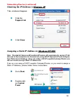
Page 33: ...same Workgroup name Click OK Checking the IP Address in Windows XP The wireless adapter equipped computers in your network must be in the same IP Address range see Getting Started in this manual for...

Page 34: ...band Routers will automatically assign IP Ad dresses to the computers on the network using DHCP Dynamic Host Configura tion Protocol technology If you are using a DHCP capable Gateway Router you will...

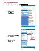
Page 35: ...35 Networking Basics continued Assigning a Static IP Address in Windows XP 2000 Double click on Network Connections Double click on Properties Right click on Local Area Connections...

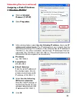
Page 36: ...ntial like 192 168 0 3 and 192 168 0 4 The subnet mask must be the same for all the computers on the network Click OK Select Use the following DNS server addresses Enter the LAN IP address of the Wire...

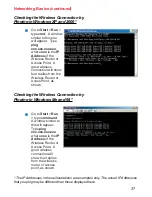
Page 37: ...Access Point A good wireless connection will show four replies from the Wireless Router or Acess Point as shown Go to Start Run type command A window similar to this will appear Type ping xxx xxx xxx...

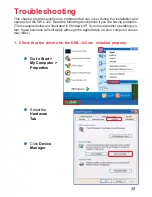
Page 38: ...erties This chapter provides solutions to problems that can occur during the installation and operation of the DWL 122 Read the following descriptions if you are having problems The examples below are...

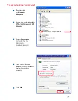
Page 39: ...apter Select Properties to check that the drivers are installed properly Look under Device Status to check that the device is working properly Click OK D Link Air DWL 122 Wireless USB Adapter D Link A...

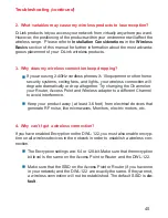
Page 40: ...n the network in order to establish a wireless con nection If you are using 2 4GHz cordless phones X 10 equipment or other home security systems ceiling fans and lights your wireless connection will d...

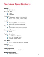
Page 41: ...95 non condensing Humidity Antenna Type Integrated microstrip diversity antenna DSSS Modulation Technique L 3 25 inches 82 5mm W 1 07 inches 27 2mm H 0 47 inches 12mm Physical Dimensions 1 2 5 5 11Mb...

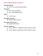
Page 42: ...e RC4 Encryption algorithm Encryption 30 000 hours MTBF DQPSK DBPSK and CCK Modulation Schemes Typical 16dBm 40mW Transmitter Output Power Typical 81dBm for 11Mbps 8 PER Packet Error Rate Receiver Sen...

Page 43: ...cal Support through our website or by phone Tech Support for customers within the United States D Link Technical Support over the Telephone 877 453 5465 24 hours a day seven days a week D Link Technic...

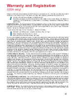
Page 44: ...ion of the product Software will substantially conform to D Link s then current functional specifications for the Software as set forth in the applicable documentation from the date of original retail...

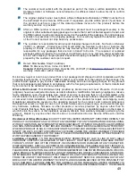
Page 45: ...odification tampering negligence misuse faulty installation lack of reasonable care repair or service in any way that is not contemplated in the documentation for the product or if the model or serial...

Page 46: ...orporation D Link Systems Inc as stipulated by the United States Copyright Act of 1976 Contents are subject to change without prior notice Copyright 2002 by D Link Corporation D Link Systems Inc All r...

Reviews: