background image


i


T

ABLE OF 

C

ONTENTS


ABOUT THIS GUIDE

....................................................1


P

URPOSE

.........................................................................................1


O

VERVIEW OF THIS 

U

SER

G

UIDE

..........................................1


INTRODUCTION

..............................................................2


F

AST 

E

THERNET 

T

ECHNOLOGY

................................................2


S

WITCHING 

T

ECHNOLOGY

.........................................................2


F

EATURES

.......................................................................................4


U

NPACKING

....................................................................................6


S

ETUP

..............................................................................................6


IDENTIFYING EXTERNAL 
COMPONENTS

....................................................................7


F

RONT 

P

ANEL

.............................................................................7


LED I

NDICATORS

.........................................................................7


R

EAR 

P

ANEL

................................................................................8


CONNECTING THE DSS-8+

................................10


PC 

TO 

DSS-8+

............................................................................10


H

UB TO 

DSS-8+

..........................................................................10


A. 10BASE-T Hub

...................................................................11


B. 100BASE-TX Hub

.............................................................11


H

UB WITHOUT 

U

PLINK 

(MDI-II) 

PORT

.................................11


A. Using straight cable

.............................................................11


B. Using crossover cable

.........................................................11


Summary of Contents for DSS-8+

Page 1: ...DSS 8 8 port 10 100Mbps Switch User s Guide Rev 03 MAR 2001 6012 9830016 Printed In Taiwan RECYCLABLE ...

Page 2: ...LOGY 2 SWITCHING TECHNOLOGY 2 FEATURES 4 UNPACKING 6 SETUP 6 IDENTIFYING EXTERNAL COMPONENTS 7 FRONT PANEL 7 LED INDICATORS 7 REAR PANEL 8 CONNECTING THE DSS 8 10 PC TO DSS 8 10 HUB TO DSS 8 10 A 10BASE T Hub 11 B 100BASE TX Hub 11 HUB WITHOUT UPLINK MDI II PORT 11 A Using straight cable 11 B Using crossover cable 11 ...

Page 3: ... 8 TO SWITCH OTHER DEVICES 11 A Using straight cable 12 B Using crossover cable 12 PORT SPEED DUPLEX MODE 12 INSTRUCTIONS FOR USE OF STACKING BRACKETS 13 RJ 45 PIN SPECIFICATION 14 TECHNICAL SPECIFICATIONS 16 ...

Page 4: ...eatures Chapter 2 Unpacking and Setup Helps you get started with the basic installation of the DSS 8 Chapter 3 Identifying External Components Describes the front panel rear panel and LED indicators of the DSS 8 Chapter 4 Connecting the DSS 8 Tells how you can connect the DSS 8 to your Ethernet network Appendix A Technical Specifications Lists the technical general physical and environmental and p...

Page 5: ...ve and smooth evolution nature and the dominating potential market base virtually guarantee cost effective and high performance Fast Ethernet solutions in the years to come 100Mbps Fast Ethernet is a new standard specified by the IEEE 802 3 LAN committee It is an extension of the 10Mbps Ethernet standard with the ability to transmit and receive data at 100Mbps while maintaining the CSMA CD Etherne...

Page 6: ... same network cabling and adapter cards For Fast Ethernet networks a DSS 8 is an effective way of eliminating problems of chaining hubs beyond the two repeater limit A DSS 8 can be used to split parts of the network into different collision domains making it possible to expand your Fast Ethernet network beyond the 205 meter network diameter limit for 100BASE TX networks DSS 8 s supporting both tra...

Page 7: ...SS 8 is expandable by cascading two or more DSS 8 s together As all ports support 200Mbps the DSS 8 can be cascaded from any port and to any number of DSS 8 s The DSS 8 is a perfect choice for sites planning to upgrade to Fast Ethernet in the future Ethernet workgroups can connect to the DSS 8 now and you can change adapters and hubs anytime later without needing to change the DSS 8 s or reconfigu...

Page 8: ...ropped packets by sending out collision signals when the port s receiving buffer is full Note that flow control is only available in half duplex mode Data forwarding rate per port is at wire speed for 100Mbps speed Data forwarding rate per port is at wire speed for 10Mbps speed Data filtering rate eliminates all error packets runts etc per port at wire speed for 100Mbps speed Data filtering rate e...

Page 9: ...nd missing or damaged please contact your local reseller for replacement Setup The setup for the DSS 8 can be performed using the following steps The surface must support at least 1 5 Kg for the DSS 8 The power outlet should be within 1 82 meters 6 feet of the DSS 8 Visually inspect the DC power jack and make sure that it is fully secured to the power adapter Make sure that there is proper heat di...

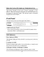
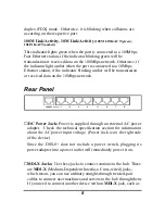
Page 10: ...t panel of the DSS 8 LED Indicator Panel Refer to the LED Indicator section for detailed information about each of the DSS 8 s LED indicators LED Indicators Power Indicator PWR This indicator lights green when the hub is receiving power otherwise it is off Loop Detect LOOP When this indicator lights amber it means that there is a loop detected then the network needs to be re configuration Full Dup...

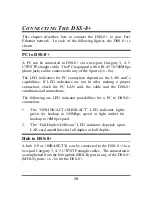
Page 11: ...ion or received data on the 10Mbps network Rear Panel DC Power Jack Power is supplied through an external AC power adapter Check the technical specification section for information about the AC power input voltage Power Jack is on the right side of the device Since the DSS 8 does not include a power switch plugging its power adapter into a power outlet will immediately power it on MDI X Jacks Use ...

Page 12: ... MDI X jack described below Uplink Jack s MDI II Use this jack to connect stations to the hub This is an MDI II Medium dependent Interface straight wired jack which means you can connect the hub to a device with an MDI X port using an ordinary straight through cable making a crossover cable unnecessary ...

Page 13: ...t after making a proper connection check the PC LAN card the cable and the DSS 8 conditions and connections The following are LED indicator possibilities for a PC to DSS 8 connection 1 The 100LINK ACT 10LINK ACT LED indicator lights green for hookup to 100Mbps speed or light amber for hookup to 10Mbps speed 2 The Full Duplex Collision LED indicator depends upon LAN card capabilities for full duple...

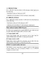
Page 14: ...plink MDI II port If a hub is not equipped with an uplink MDI II port connection can be made using either straight cable or crossover cable A Using straight cable When using straight cable the connection can be made from the uplink MDI II port of the DSS 8 to any port of the hub B Using crossover cable When using crossover cable the connection can be made from any MDI X ports of the DSS 8 to any p...

Page 15: ... The 100LINK ACT 10LINK ACT LED indicator light green for hookup to 100Mbps speed or light amber for hookup to 10Mbps speed 2 The Full Duplex Collision LED indicator depends upon LAN card capabilities for full duplex or half duplex Port Speed Duplex Mode After plugging the selected cable to a specific port the system uses auto negotiation to determine the transmission mode for any new twisted pair...

Page 16: ...evice as shown in the diagram below Be sure each bracket is positioned correctly Note when clicking each bracket into place the round feet on the bottom of the device will line up with the round holes on the bracket The brackets are designed to fit snugly in place Please do not force them The brackets are now ready for stacking devices See the diagram below ...

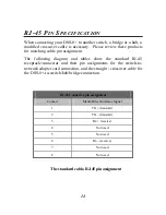
Page 17: ...and tables show the standard RJ 45 receptacle connector and their pin assignments for the switch to network adapter card connection and the straight crossover cable for the DSS 8 to switch hub bridge connection RJ 45 Connector pin assignment Contact Media Direct Interface Signal 1 TX transmit 2 TX transmit 3 Rx receive 4 Not used 5 Not used 6 Rx receive 7 Not used 8 Not used The standard cable RJ ...

Page 18: ...e following shows straight cable and crossover cable connection Straight cable for DSS 8 uplink MDI II port to switch Hub or other devices connection Crossover cable for DSS 8 MDI X port to switch hub or other network devices MDI X port connection ...

Page 19: ... Transfer Rate Ethernet 10Mbps half duplex 20Mbps full duplex Fast Ethernet 100Mbps half duplex 200Mbps full duplex Topology Star Network Cables 10BASET 2 pair UTP Cat 3 4 5 100 m EIA TIA 568 100 ohm STP 100 m 100BASE TX 2 pair UTP Cat 5 100 m EIA TIA 568 100 ohm STP 100 m Number of Ports 8 x 10 100Mbps NWay ports Uplink Port MDI II RJ 45 shared with port 1 share with port 1 ...

Page 20: ...0 90 Storage 5 90 Dimensions 190 x116 x 32 mm W x H x D EMI FCC Class B CE Mark B VCCI II Performance Transmissio n Method Store and forward RAM Buffer 256KBytes per device Filtering Address Table 16K entries per device Packet Filtering For warding Rate 10Mbps Ethernet 14 880 pps 100Mbps Fast Ethernet 148 800 pps MAC Address Learning Automatic update ...

Page 21: ...wing measures Reorient or relocate the receiving antenna Increase the separation between the equipment and receiver Connect the equipment into an outlet on a circuit different from that to which the receiver is connected Consult the dealer or an experienced radio TV technician for help Shielded interface cables must be used in order to comply with emission limits You are cautioned that changes or ...

Page 22: ...lies and fans One 1 Year Power Supplies and Fans One 1 Year Spare parts and spare kits Ninety 90 days D Link s sole obligation shall be to repair or replace the defective Hardware at no charge to the original owner Such repair or replacement will be rendered by D Link at an Authorized D Link Service Office The replacement Hardware need not be new or of an identical make model or part D Link may in...

Page 23: ...ction or if D Link determines in its sole discretion that it is not practical to replace the non conforming Software the price paid by the original licensee for the non conforming Software will be refunded by D Link provided that the non conforming Software and all copies thereof is first returned to D Link The license granted respecting any Software for which a refund is given automatically termi...

Page 24: ...dance with the foregoing requirements or that is determined by D Link not to be defective or non conforming What Is Not Covered This limited warranty provided by D Link does not cover Products that have been subjected to abuse accident alteration modification tampering negligence misuse faulty installation lack of reasonable care repair or service in any way that is not contemplated in the documen...

Page 25: ...F GOODWILL WORK STOPPAGE COMPUTER FAILURE OR MALFUNCTION LOSS OF INFORMATION OR DATA CONTAINED IN STORED ON OR INTEGRATED WITH ANY PRODUCT RETURNED TO D LINK FOR WARRANTY SERVICE RESULTING FROM THE USE OF THE PRODUCT RELATING TO WARRANTY SERVICE OR ARISING OUT OF ANY BREACH OF THIS LIMITED WARRANTY EVEN IF D LINK HAS BEEN ADVISED OF THE POSSIBILITY OF SUCH DAMAGES THE SOLE REMEDY FOR A BREACH OF T...

Page 26: ...ems Inc All other trademarks belong to their respective proprietors Copyright Statement No part of this publication may be reproduced in any form or by any means or used to make any derivative such as translation transformation or adaptation without permission from D Link Corporation D Link Systems Inc as stipulated by the United States Copyright Act of 1976 ...

Reviews: