background image

DMS-1250 Series Multi-G Ethernet Smart Managed Switch Hardware Installation Guide


1.


Introduction 

Switch Description 

Package Contents 

Features 

Front Panel Components 

Rear Panel Components 

Side Panel Components 


Switch Description 

The DMS-1250 Series is D-Link’s next generation Smart Managed Switch. The Switch has a combination of 

2.5GBASE-T and SFP+ ports that may be used to connect various networking devices to the Switch. The SFP+ ports 

are used with fiber-optical transceiver cabling in order to uplink various other networking devices for a 1Gbps or 10 

Gbps link that may span great distances. 
 
The D-Link DMS-1250 Series includes the following switches: 


DMS-1250-10S: 

Eight 2.5GE Smart Managed switch with 2 SFP+ ports


DMS-1250-10SP:


Eight 2.5GE POE Smart Managed switch with 2 SFP+ ports.


DMS-1250-10SPL:


Eight 2.5GE POE Smart Managed switch with 2 SFP+ ports.


DMS-1250-12TP:


Eight 2.5GE POE Smart Managed switch with 2 SFP+ ports and 2 10GE ports


Package Contents 

Open the shipping carton of the Switch and carefully unpack its contents. The box should contain the following items: 

  One DMS-1250 Series switch. 

  One 

Safety Notice

  One AC power cord or power adaptor. 

  One rack mounting kit (two brackets and screws). 

  Four rubber feet with adhesive backing. 


One power cord retainer set (if with AC inlet power port).


  One RJ45 console cable 

  Additional documents based on local regulation requirement (optional). 

If any item is missing or damaged, please contact your local D-Link reseller for replacement. 

Features 

The list of features below highlights the significant features of the Switch. 

  Supports a 16K MAC address table. 

  Supports Flow Control (802.3x) in full-duplex compliant. 

  Supports Jumbo Frames of up to 12KB. 

  Supports Spanning Tree with 802.1D 2004 STP/RSTP and 802.1Q 2005 MSTP. 

  Supports Loopback Detection (LBD). 

  Supports Link Aggregation (802.3ad and 802.3AX) with a maximum of 8 groups per Switch. 

  Supports Port Mirroring. 

  Supports Layer 2 Multicast Filtering. 

  Supports IGMP Snooping (v1, v2, v3 awareness) with up to 256 snooping groups and 128 static multicast 

addresses. MLD Snooping (v1, v2 awareness) with up to 256 snooping groups and 64 static multicast 

addresses. IGMP Snooping and MLD Snooping share 128 static groups and 256 snooping groups. 

  Supports Virtual LAN (802.1Q) with up to 4K VLAN groups. 

  Supports Port-based VLAN. 

  Supports Asymmetric VLAN. 

Summary of Contents for DMS-1250 Series

Page 1: ...Multi G Ethernet Smart Managed Switch DMS 1250 Series Hardware Installation Guide Version 1 02 12 25 2023...

Page 2: ...t to the following two conditions 1 This device may not cause harmful interference and 2 this device must accept any interference received including interference that may cause undesired operation CE...

Page 3: ...ower 12 Installing Power Cord Retainer 13 Switch to an End Node 16 Switch to Another Switch 16 Switch to a Server 17 Management Options 18 Connecting to the Console Port 18 Connecting to the Switch fo...

Page 4: ...s series will simply be referred to as the Switch throughout this manual Typographical Conventions Convention Description Boldface Font This convention is used to place emphasis on keywords It also in...

Page 5: ...ollowing items One DMS 1250 Series switch One Safety Notice One AC power cord or power adaptor One rack mounting kit two brackets and screws Four rubber feet with adhesive backing One power cord retai...

Page 6: ...covery Protocol LLDP with LLDP MED Supports Accessibility using multiple interfaces like the Command Line Interface CLI Web based Graphical User Interface Web based GUI and more Supports Telnet Server...

Page 7: ...d support a wide collection of SFP SFP transceivers 100 1000 2 5G 5G 10GBASE T RJ45 Ports The DMS 1250 12TP Switch supports 2 RJ45 10 Gbps Ethernet ports These ports can operate at 100 1000 2500 5000...

Page 8: ...ower is sufficient and below the guard band threshold LED Mode DMS 1250 10SP DMS 1250 12TP DMS 1250 10SPL Green Solid light A LED Mode push button is allowed to select the port Link ACT status or PoE...

Page 9: ...hen there is a secure 1000Mbps connection at the port Blinking When there is reception or transmission occurring at the port Off Light off No link LED Per PoE Port PoE Status Green Solid light Power d...

Page 10: ...10GBASE LRM Multi Mode 200M SFP Transceiver DEM 410T 10GBASE T Copper SFP transceiver 30M WDM BiDi SFP Transceivers Supported DEM 436XT BXD 10GBASE LR single mode 20 km TX 1330 nm RX 1270 nm without D...

Page 11: ...ponent Description Security Lock Provide a Kensington compatible security lock to be able to connect to a secure immovable device Insert the lock into the notch and turn the key to secure the lock The...

Page 12: ...ate internal heat and facilitate internal air circulation Do not block these openings Leave at least 4 inches of space at the sides of the Switch for proper ventilation Without proper heat dissipation...

Page 13: ...f the fan s will change DMS 1250 10S Fanless DMS 1250 10SP DMS 1250 12TP 5 speed Smart FAN setting as below o T1 10 C FAN Duty 30 o T2 25 C FAN Duty 40 o T3 40 C FAN Duty 60 o T4 50 C FAN Duty 70 o T5...

Page 14: ...ng electromagnetic field generators such as motors vibration dust and direct exposure to sunlight Installing the Switch without a Rack This section is used to guide the user through installing the Swi...

Page 15: ...ided Figure 2 3 Installing the Switch in a Rack Make sure that there is adequate space around the Switch to allow for proper airflow ventilation and cooling Installing Transceivers into the Transceive...

Page 16: ...Sub chapter J in accordance with FDA CDRH requirements IEC EN 60825 1 2 2007 2nd edition or later European Standard REMARQUE N utilisez que des modules optiques enfichables et des c bles connexion dir...

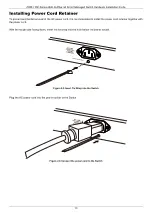
Page 17: ...l of the AC power cord it is recommended to install the power cord retainer together with the power cord With the rough side facing down insert the tie wrap into the hole below the power socket Figure...

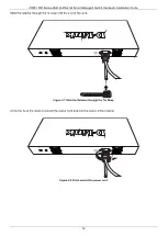
Page 18: ...stallation Guide 14 Slide the retainer through the tie wrap until the end of the cord Figure 2 7 Slide the Retainer through the Tie Wrap Circle the tie of the retainer around the power cord and into t...

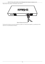
Page 19: ...allation Guide 15 Fasten the tie of the retainer until the power cord is secured Figure 2 9 Secure the power cord All the product pictures shown are for illustration purposes only Actual product appea...

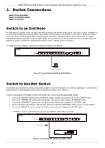
Page 20: ...onnecting the Switch to an End Node Switch to Another Switch The Switch can be used to connect to any other switch or hub in the network This network topology is used when the Switch does not have eno...

Page 21: ...Guide 17 Switch to a Server The Switch is ideal for connecting to a network backbone server or server farm The RJ45 ports Port 11 12 operate at a speed of 100Mbps 1G 2 5G 5G 10G The SFP ports operate...

Page 22: ...Web UI can be accessed from any computer running web browsing software from its LAN port when it is connected to any of the RJ45 or SFP SFP ports The Web UI on the Switch can also be accessed using a...

Page 23: ...acle on the back of the Switch After correctly configuring the terminal settings and re inserting the power cable the boot procedure will appear in the terminal After the boot sequence has been comple...

Page 24: ...witch config In the example above Enter the configure terminal command to enter the Global Configuration Mode Press ENTER Enter the username NewUser password 12345 command to create a user account wit...

Page 25: ...v1 and SNMPv2c user authentication is accomplished using community strings which function like passwords The remote user SNMP application and the Switch SNMP must use the same community string SNMP pa...

Page 26: ...dard MIB II Management Information Base module Consequently values for MIB objects can be retrieved from any SNMP based network management software In addition to the standard MIB II the Switch also s...

Page 27: ...er The web browser acts as a universal access tool and can communicate directly with the Switch using the HTTP or HTTPS SSL protocol The following web browsers are supported Internet Explorer version...

Page 28: ...sing the ENTER key the following authentication window should appear as shown below Figure 5 2 Web UI Login Window Enter the User Name and Password in the corresponding fields and click Login This wil...

Page 29: ...is area displays a graphical near real time image of the front panel of the Switch This area displays the Switch s ports and expansion modules It also shows port activity based on a specific mode Some...

Page 30: ...ding the Layer 3 functionality of the Switch can be viewed and configured in this folder QoS Features regarding the Quality of Service functionality of the Switch can be viewed and configured in this...

Page 31: ...54V 2 78A external power adapter Security Lock Provides a Kensington compatible security lock on the rear panel of the Switch to be able to connect to a secure immovable device Insert the lock into t...

Page 32: ...34 kgs 2 95 lbs EMC Certifications CE Class A FCC Class A ISED Class A VCCI Class A RCM Class A BSMI Class A Safety Certifications IEC60950 1 IEC62368 1 UL CSA62368 1 BSMI Class A Performance Feature...

Page 33: ...from the device Keep the system away from radiators and heat sources Also do not block cooling vents Do not spill food or liquids on system components and never operate the product in a wet environme...

Page 34: ...15V 60Hz is used mostly in North and South America as well as Far Eastern countries like as South Korea and Taiwan 100V 50Hz is used mostly in Eastern Japan and 100V 60Hz in Western Japan 230V 50Hz is...

Page 35: ...e prise et n liminez pas la broche de mise la masse du c ble Si un c ble de rallonge est n cessaire utilisez un c ble 3 fils avec des fiches correctement mises la terre Respectez les caract ristiques...

Page 36: ...st item in the rack first Make sure that the rack is level and stable before extending a component from the rack Use caution when pressing the component rail release latches and sliding a component in...

Page 37: ...hassis The following steps can also be taken prevent damage from electrostatic discharge ESD When unpacking a static sensitive component from its shipping carton do not remove the component from the a...

Page 38: ...ione online Documenta o online Dokumentasi online www dlink com resources business Online Support Documentazione online Online Dokumentation Documentaci n en l nea Documentazione online Suporte t cnic...

Reviews: