remote system for monitoring and configuring the Switch. Both ports require their
respective cables included with the Switch, to establish the physical connection.
NOTE:
When an active console connection is made to both the RJ-45 console port
and the mini-USB console port at the same time, the mini-USB console port will
have higher priority.
Connecting to the RJ-45 Console Port
To use the RJ-45 console port, the following equipment is needed:
A terminal or a computer with both an RS-232 serial port and terminal emulation
software
A console cable with a male DB9 connector on one end and an RJ-45 connection
on the other
To connect the RJ-45 console port on the Switch to the computer:
Connect the male DB9 connector on the console cable (shipped with the Switch) to
the RS-232 serial port on the computer running terminal emulation software then
insert the RJ-45 connector into the RJ-45 console port on the front of the Switch.
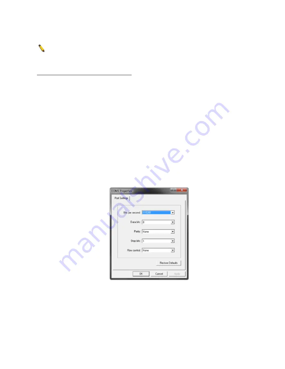
To configure the terminal emulation software as follows:
Select the appropriate serial port (COM1 or COM2).
Set the data rate to 115200 baud.
Set the data format to 8 data bits, 1 stop bit, and no parity.
Set flow control to none.
Figure 13 — COM Port Configuration
To be able to view the boot procedure, the Switch needs to be rebooted. The simplest way,
at this stage, to reboot the Switch is to unplug and re-insert the power cable from and into
the power receptacle on the back of the Switch. After correctly configuring the terminal
settings and re-inserting the power cable, the boot procedure will appear in the terminal.
9


