background image

xStack® DGS-3620 Series Managed Switch Web UI Reference Guide 

220 


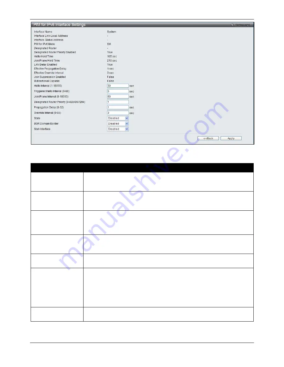
Figure 5-94 PIM for IPv6 Interface Settings – Edit window 

 
The fields that can be configured are described below: 

Parameter 

Description 

Hello Interval (1-18000) 

Enter the time between issuing hello packets to find neighboring routers. A value of 

zero represents an ‘infinite’ interval, and indicates that periodic PIM for IPv6 Hello 

message should not be sent on this interface. 

Triggered Hello 
Interval (0-60) 

Enter the maximum time before the router sends a triggered PIM Hello message on 

the specified interface. A value of zero has no special meaning and indicates that 

triggered PIM for IPv6 Hello message should always be sent immediately. 

Join/Prune Interval  
(1-18000) 

Enter the frequency at which this router sends PIM for IPv6 Join/Prune messages on 

this PIM for IPv6 interface. A value of zero represents an ‘infinite’ interval, and 

indicates that periodic PIM for IPv6 Join/Prune messages should not be sent on this 

interface. 

Designated Router 
Priority (0-4294967294) 

Enter the Designated Router Priority value inserted into the DR Priority option in PIM 

for IPv6 Hello message transmitted on this interface. Numerically higher values for 

this parameter indicate higher priorities. 

Propagation Delay (0-
32) 

Enter the expected propagation delay between the PIM for IPv6 routers on this 

network or link. 

Override Interval (0-65) 

Enter a value that this router inserts into the Override_Interval field of the LAN Prune 

Delay option in the PIM for IPv6 Hello messages it sends on this interface. When 

overriding a prune, PIM for IPv6 routers pick random time duration up to the value of 

this object. The more PIM for IPv6 routers that are active on a network, the more 

likely it is that the prune will be overridden after a small proportion of this time has 

elapsed. The more PIM for IPv6 routers are active on this network, the larger this 

object should be to obtain an optimal spread of prune override latencies. 

State 

Use the drop-down menu to enable or disable the PIM for IPv6 for the above IPv6 

interface. By default, the PIM for IPv6 protocol state is disabled on an interface. 

Summary of Contents for DGS-3620-28PC-SI

Page 1: ......

Page 2: ...poration is strictly forbidden Trademarks used in this text D Link and the D LINK logo are trademarks of D Link Corporation Microsoft and Windows are registered trademarks of Microsoft Corporation Other trademarks and trade names may be used in this document to refer to either the entities claiming the marks and names or their products D Link Corporation disclaims any proprietary interest in trade...

Page 3: ...mation Settings 9 Port Configuration 10 Port Settings 10 Port Description Settings 11 Port Error Disabled 12 Port Auto Negotiation Information 13 Jumbo Frame Settings 14 PoE 14 PoE System Settings 15 PoE Port Settings 16 Serial Port Settings 17 Warning Temperature Settings 17 System Log configuration 18 System Log Settings 18 System Log Server Settings 18 System Log 19 System Log Trap Settings 20 ...

Page 4: ...gs 51 SNMP Linkchange Traps Settings 51 SNMP View Table Settings 52 SNMP Community Table Settings 53 SNMP Group Table Settings 54 SNMP Engine ID Settings 55 SNMP User Table Settings 55 SNMP Host Table Settings 56 SNMPv6 Host Table Settings 57 RMON Settings 58 SNMP Community Encryption Settings 58 SNMP Community Masking Settings 58 Telnet Settings 59 Web Settings 59 Chapter 4 L2 Features 61 VLAN 61...

Page 5: ...cast VLAN 120 Multicast Filtering 126 IPv4 Multicast Filtering 126 IPv6 Multicast Filtering 128 Multicast Filtering Mode 131 ERPS Settings 131 LLDP 135 LLDP 135 LLDP MED 143 NLB FDB Settings 145 PTP 146 PTP Global Settings 146 PTP Port Settings 147 PTP Boundary Clock Settings 148 PTP Boundary Port Settings 149 PTP Peer to Peer Transparent Port Settings 150 PTP Clock Information 151 PTP Port Inform...

Page 6: ...bal Settings 232 BGP Aggregate Address Settings 234 BGP Network Settings 234 BGP Dampening Settings 235 BGP Peer Group Settings 236 BGP Neighbor 237 BGP Reflector Settings 245 BGP Confederation Settings 246 BGP AS Path Access Settings 247 BGP Community List Settings 248 BGP Trap Settings 249 BGP Clear Settings 249 BGP Summary Table 250 BGP Routing Table 251 BGP Dampened Route Table 252 BGP Flap St...

Page 7: ...thenticator Session Statistics 328 Authenticator Diagnostics 329 Initialize Port based Port s 330 Initialize Host based Port s 331 Reauthenticate Port based Port s 331 Reauthenticate Host based Port s 331 RADIUS 332 Authentication RADIUS Server Settings 332 RADIUS Accounting Settings 333 RADIUS Authentication 333 RADIUS Account Client 335 IP MAC Port Binding IMPB 336 IMPB Global Settings 336 IMPB ...

Page 8: ...on Settings 368 NetBIOS Filtering Settings 369 DHCP Server Screening 370 DHCP Server Screening Port Settings 370 DHCP Offer Permit Entry Settings 371 Access Authentication Control 371 Enable Admin 372 Authentication Policy Settings 373 Application Authentication Settings 374 Authentication Server Group Settings 374 Authentication Server Settings 376 Login Method Lists Settings 377 Enable Method Li...

Page 9: ...e 421 CFM MP Table 422 Ethernet OAM 422 Ethernet OAM Settings 422 Ethernet OAM Configuration Settings 423 Ethernet OAM Event Log 424 Ethernet OAM Statistics 425 DULD Settings 426 Cable Diagnostics EI Mode Only 427 Chapter 11 Monitoring 429 Utilization 429 CPU Utilization 429 DRAM Flash Utilization 430 Port Utilization 430 Statistics 431 Port Statistics 431 Packet Size 438 Mirror 440 Port Mirror Se...

Page 10: ...ownload Configuration from TFTP 454 Download Configuration from RCP 455 Download Configuration from HTTP 455 Upload Configuration 456 Upload Configuration to TFTP 456 Upload Configuration to RCP 456 Upload Configuration to HTTP 457 Upload Log File 458 Upload Log to TFTP 458 Upload Log to RCP 458 Upload Log to HTTP 459 Reset 459 Reboot System 460 Appendices 461 Appendix A Mitigating ARP Spoofing At...

Page 11: ...nt is also used to represent filenames program names and commands For example use the copy command Boldface Typewriter Font Indicates commands and responses to prompts that must be typed exactly as printed in the manual Initial capital letter Indicates a window name Names of keys on the keyboard have initial capitals For example Click Enter Menu Name Menu Option Menu Name Menu Option Indicates the...

Page 12: ...r available at the Switch s location o 115 volts V 60 hertz Hz in most of North and South America and some Far Eastern countries such as South Korea and Taiwan o 100 V 50 Hz in eastern Japan and 100 V 60 Hz in western Japan o 230 V 50 Hz in most of Europe the Middle East and the Far East Also be sure that attached devices are electrically rated to operate with the power available in your location ...

Page 13: ...e full weight of the rack rests on the floor Install front and side stabilizers on a single rack or front stabilizers for joined multiple racks before working on the rack Always load the rack from the bottom up and load the heaviest item in the rack first Make sure that the rack is level and stable before extending a component from the rack Use caution when pressing the component rail release latc...

Page 14: ...llowing steps can also be taken prevent damage from electrostatic discharge ESD 1 When unpacking a static sensitive component from its shipping carton do not remove the component from the antistatic packing material until ready to install the component in the system Just before unwrapping the antistatic packaging be sure to discharge static electricity from your body 2 When transporting a sensitiv...

Page 15: ...e same internal switching software and configure it Thus all settings encountered in web based management are the same as those found in the console program Login to the Web Manager To begin managing the Switch simply run the browser installed on your computer and point it to the IP address you have defined for the device The URL in the address bar should read something like http 123 123 123 123 w...

Page 16: ...splay Open folders and click the hyperlinked menu buttons and subfolders contained within them to display menus Click the D Link logo to go to the D Link website Area 2 Presents a graphical near real time image of the front panel of the Switch This area displays the Switch s ports console and management port showing port activity Some management functions including save reboot download and upload ...

Page 17: ...gure features regarding the Layer 3 functionality of the Switch QoS In this section the user will be able to configure features regarding the Quality of Service functionality of the Switch ACL In this section the user will be able to configure features regarding the Access Control List functionality of the Switch Security In this section the user will be able to configure features regarding the Sw...

Page 18: ...o the Switch To return to the Device Information window after viewing other windows click the DGS 3620 Series link The Device Information window shows the Switch s MAC Address assigned by the factory and unchangeable the Boot PROM Version Firmware Version Hardware Version and many other important types of information This is helpful to keep track of PROM and firmware updates and to obtain the Swit...

Page 19: ...em Location and System Contact to aid in defining the Switch To view the following window click System Configuration System Information Settings as show below Figure 2 2 System Information Settings window The fields that can be configured are described below Parameter Description System Name Enter a system name for the Switch if so desired This name will identify it in the Switch network System Lo...

Page 20: ... Choose the port or sequential range of ports using the From Port and To Port drop down menus 2 Use the remaining drop down menus to configure the parameters described below The fields that can be configured are described below Parameter Description Unit Select the unit you wish to configure From Port To Port Select the appropriate port range used for the configuration here State Toggle the State ...

Page 21: ...arious port configurations Ports configured for full duplex use 802 3x flow control half duplex ports use backpressure flow control and Auto ports use an automatic selection of the two The default is Disabled Connection Here the current connection speed will be displayed MDIX Auto Select auto for auto sensing of the optimal type of cabling Normal Select normal for normal cabling If set to normal s...

Page 22: ...lected ports If configuring the Combo ports the Medium Type defines the type of transport medium to be used whether Copper or Fiber Description Users may then enter a description for the chosen port s Click the Apply button to implement changes made Port Error Disabled The following window displays the information about ports that have been disconnected by the Switch when a packet storm occurs or ...

Page 23: ...whether enabled or disabled Reason Describe the reason why the port has been error disabled such as it has become a shutdown port for storm control Port Auto Negotiation Information The following window displays the detailed auto negotiation information To view the following window click System Configuration Port Configuration Port Auto Negotiation Information as show below Figure 2 6 Port Auto Ne...

Page 24: ...led When disabled the maximum frame size is 1536 bytes When enabled the maximum frame size is 13312 bytes Unit Select the unit you wish to configure From Port To Port Select the appropriate port range used for the configuration here State Use the drop down menu to enable the Jumbo Frame for the port Click the Apply button to implement changes made PoE The DGS 3620 28PC and DGS 3620 52P switches su...

Page 25: ...ngs window The following parameters can be configured Parameter Description Unit Select the unit you wish to configure Tick the All check box to select all units Power Limit 37 740 Sets the limit of power to be used from the Switch s power source to PoE ports The user may configure a Power Limit between 1 and 740W for the DGS 3620 28PC and DGS 3620 52P The default setting is 740W Power Disconnect ...

Page 26: ...e level of priority the port ID will be used to determine the priority The lower port ID has higher priority The setting of priority will affect the order of supplying power Whether the disconnect method is set to deny low priority port the priority of each port will be used by the system to manage the supply of power to ports Power Limit This function is used to configure the per port power limit...

Page 27: ... from the following options 2 5 10 15 minutes or Never The default setting is 10 minutes Data Bits Display the data bits used for the serial port connection Parity Bits Display the parity bits used for the serial port connection Stop Bits Display the stop bits used for the serial port connection Click the Apply button to implement changes made Warning Temperature Settings This window allows the us...

Page 28: ...ave Mode Use the drop down menu to choose the method for saving the switch log to the flash memory The user has three options On Demand Users who choose this method will only save log files when they manually tell the Switch to do so either using the Save Log link in the Save folder Time Interval Users who choose this method can configure a time interval by which the Switch will save the log files...

Page 29: ...Facility Use the drop down menu to select Local 0 Local 1 Local 2 Local 3 Local 4 Local 5 Local 6 or Local 7 UDP Port 514 or 6000 65535 Type the UDP port number used for sending Syslog messages The default is 514 Status Choose Enabled or Disabled to activate or deactivate Click the Apply button to accept the changes made Click the Delete All button to remove all servers configured System Log Users...

Page 30: ...s hours minutes and seconds since the Switch was last restarted Level Display the level of the log entry Log Text Display text describing the event that triggered the history log entry Click the Find button to display the log in the display section according to the selection made Click the Clear Log button to clear the entries from the log in the display section Click the Clear Attack Log button t...

Page 31: ...agent and the Switch s log for analysis Severity Level This drop down menu allows you to select the level of messages that will be sent The options are Emergency 0 Alert 1 Critical 2 Error 3 Warning 4 Notice 5 Information 6 and Debug 7 Click the Apply button to accept the changes made Time Range Settings Time range is a time period that the respective function will take an effect on such as ACL Fo...

Page 32: ...Time Range Information table in the bottom half of the window shown above Port Group Settings This window is used to create port groups and add or delete ports from the port groups To view the following window click System Configuration Port Group Settings as show below Figure 2 18 Port Group Settings window The fields that can be configured are described below Parameter Description Group Name Ent...

Page 33: ...tor Power User User Configuration Read Write Read Write partly Read Write partly No Network Monitoring Read Write Read Write Read only Read only Community Strings and Trap Stations Read Write Read only Read only Read only Update Firmware and Configuration Files Read Write No No No System Utilities Read Write Read only Read only Read only Factory Reset Read Write No No No User Account Management Ad...

Page 34: ...if the user has used the Enable Admin function to replace its privilege Stacking From firmware release v1 00 of this Switch the Switch now supports switch stacking where a set of 12 switches can be combined to be managed by one IP address through Telnet the GUI interface web the console port or through SNMP Each switch of this series has two stacking ports located at the rear of the device which c...

Page 35: ...switches constitute the rest of the switch stack and although not Primary or Backup Masters they can be placed into these roles when these other two roles fail or are removed from the stack Slave switches perform operations requested by the master monitor the status of neighbor switches in the stack and the stack topology and adhere to the Backup Master s commands once it becomes a Primary Master ...

Page 36: ...as ARP will be cleared as well Then the Backup Master will begin backing up the Primary Master when the database synchronization has been completed by the stack If the Primary Master is removed the Backup Master will assume the Primary Master s role and a new Backup Master will be chosen using the election process Switches in the stack will clear the configurations of the unit removed and dynamica...

Page 37: ...ero after the stacking has stabilized Current Box ID The Box ID of the switch in the stack to be configured New Box ID The new box ID of the selected switch in the stack that was selected in the Current Box ID field The user may choose any number between 1 and 12 to identify the switch in the switch stack Auto will automatically assign a box number to the switch in the switch stack Priority 1 63 D...

Page 38: ...and is used to translate IP addresses to MAC addresses To view the following window click Management ARP Static ARP Settings as show below Figure 3 1 Static ARP Settings window The fields that can be configured are described below Parameter Description ARP Aging Time 0 65535 The ARP entry age out time in minutes The default is 20 minutes IP Address The IP address of the ARP entry MAC Address The M...

Page 39: ...rce IP and destination IP are in the same interface To view the following window click Management ARP Proxy ARP Settings as show below Figure 3 2 Proxy ARP Settings window Click the Edit button to re configure the specific entry and select the proxy ARP state of the IP interface By default both the Proxy ARP State and Local Proxy ARP State are disabled ARP Table Users can display current ARP entri...

Page 40: ...uest packet that is sent by an IP address that match the system s own IP address In this case the system knows that somebody out there uses an IP address that is conflict with the system In order to reclaim the correct host of this IP address the system can send out the gratuitous ARP request packets for this duplicate IP address Gratuitous ARP Learning Normally the system will only learn the ARP ...

Page 41: ...not be sent periodically By default the interval time is 0 Click the Apply button located in the Gratuitous ARP Trap Log section to accept the changes made in this section Click the Apply button located in the Gratuitous ARP Periodical Send Interval section to accept the changes made in this section IPv6 Neighbor Settings The user can configure the Switch s IPv6 neighbor settings The Switch s curr...

Page 42: ...it through the Ethernet The Web manager will display the Switch s current IP settings NOTE The Switch s factory default IP address is 10 90 90 90 with a subnet mask of 255 0 0 0 and a default gateway of 0 0 0 0 To view the following window click Management IP Interface System IP Address Settings as show below Figure 3 7 System IP Address Settings window The fields that can be configured are descri...

Page 43: ...State Use the drop down menu to enable or disable the configuration on this interface If the state is disabled the IP interface cannot be accessed IP Address This field allows the entry of an IPv4 address to be assigned to this IP interface Subnet Mask A Bitmask that determines the extent of the subnet that the Switch is on Should be of the form xxx xxx xxx xxx where each xxx is a number represent...

Page 44: ... Interface Name Enter the name of the IP interface being created IPv4 Address Enter the IPv4 address used Subnet Mask Enter the IPv4 subnet mask used VLAN Name Enter the VLAN Name used Interface Admin State Use the drop down menu to enable or disable the Interface Admin State Secondary Interface Tick the check box to use this Interface as a Secondary Interface When the primary IP is not available ...

Page 45: ...State Click the Apply button to accept the changes made for each individual section Click the Back button to discard the changes made and return to the previous page Click the IPv6 Edit button to see the following window Figure 3 11 IPv6 Interface Settings window The fields that can be configured or displayed are described below Parameter Description Interface Name Display the IPv6 interface name ...

Page 46: ...ion When Enabled it indicates that hosts receiving this RA must use a stateful address configuration protocol to obtain the address configuration information Set to Disabled to stop hosts receiving this RA from using a stateful address configuration protocol to obtain the address configuration information Min Router AdvInterval 3 1350 Enter the minimum time allowed between sending unsolicited mult...

Page 47: ...y Click the Delete All button to remove all the entries listed in the table Click the Edit button to re configure the specific entry Click the Delete button to remove the specific entry Click the Add or Edit button to see the following window Figure 3 15 Loopback Interface Settings Add Edit window The fields that can be configured are described below Parameter Description Interface Name The name o...

Page 48: ...ch s built in power saving feature When power saving is enabled a port which has a link down status will be turned off to save power to the Switch This will not affect the port s capabilities when the port status is link up Users can also configure Password Encryption on the Switch To view the following window click Management Management Settings as show below Figure 3 16 Management Settings windo...

Page 49: ... D Link Green Technologies go to http green dlink com for more details Out of Band Management Settings This window is used to configure the out of band management port settings To view the following window click Management Out of Band Management Settings as show below Figure 3 17 Out of Band management Settings window The fields that can be configured are described below Parameter Description IP A...

Page 50: ...roadcast domain however a single switch can only belong to one group If multiple VLANs are configured the SIM group will only utilize the default VLAN on any switch SIM allows intermediate devices that do not support SIM This enables the user to manage switches that are more than one hop away from the CS The SIM group is a group of switches that are managed as a single entity The Switch may take o...

Page 51: ...ature is accomplished through the use of Discover packets and Maintenance packets that previously set SIM members will emit after a reboot Once a MS has had its MAC address and password saved to the CS s database if a reboot occurs in the MS the CS will keep this MS information in its database and when a MS has been rediscovered it will add the MS back into the SIM tree automatically No configurat...

Page 52: ...y Interval 30 90 The user may set the discovery protocol interval in seconds that the Switch will send out discovery packets Returning information to a Commander Switch will include information about other switches connected to it Ex MS CaS The user may set the Discovery Interval from 30 to 90 seconds The default value is 30 seconds Hold Time Count 100 255 This parameter may be set for the time in...

Page 53: ...ays the number of the physical port on the CS that the MS or CaS is connected to The CS will have no entry in this field Speed Displays the connection speed between the CS and the MS or CaS Remote Port Displays the number of the physical port on the MS or CaS to which the CS is connected The CS will have no entry in this field MAC Address Displays the MAC Address of the corresponding Switch Model ...

Page 54: ...ommander switch Member switch of other group Layer 3 commander switch Layer 2 candidate switch Commander switch of other group Layer 3 candidate switch Layer 2 member switch Unknown device Non SIM devices In the Topology view window the mouse plays an important role in configuration and in viewing device information Setting the mouse cursor over a specific device in the topology window tool tip wi...

Page 55: ...rsor over a line between two devices will display the connection speed between the two devices as shown below Figure 3 23 Port Speed Utilizing the Tool Tip Right clicking on a device will allow the user to perform various functions depending on the role of the Switch in the SIM group and the icon associated with it Right Click Group Icon ...

Page 56: ...ast six digits of the MAC Address to identify it Module Name Displays the full module name of the switch that was right clicked MAC Address Displays the MAC Address of the corresponding Switch Remote Port No Displays the number of the physical port on the MS or CaS that the CS is connected to The CS will have no entry in this field Local Port No Displays the number of the physical port on the CS t...

Page 57: ... clicking a Candidate icon The following options may appear for the user to configure Collapse To collapse the group that will be represented by a single icon Expand To expand the SIM group in detail Add to group Add a candidate to a group Clicking this option will reveal the following dialog box for the user to enter a password for authentication from the Candidate Switch before being added to th...

Page 58: ...ith the latest status View Topology Display the Topology view About Will display the SIM information including the current SIM version Help Figure 3 32 About window Firmware Upgrade This screen is used to upgrade firmware from the Commander Switch to the Member Switch Member Switches will be listed in the table and will be specified by Port port on the CS where the MS resides MAC Address Model Nam...

Page 59: ...rotocol SNMP is an OSI Layer 7 Application Layer designed specifically for managing and monitoring network devices SNMP enables network management stations to read and modify the settings of gateways routers switches and other network devices Use SNMP to configure system features for proper operation monitor performance and detect potential problems in the Switch switch group or network Managed de...

Page 60: ...t or network manager Typical traps include trap messages for Authentication Failure Topology Change and Broadcast Multicast Storm Traps The Switch in the Management Information Base MIB stores management and counter information The Switch uses the standard MIB II Management Information Base module Consequently values for MIB objects can be retrieved from any SNMP based network management software ...

Page 61: ...an be configured are described below Parameter Description SNMP Traps Enable this option to use the SNMP Traps feature SNMP Authentication Trap Enable this option to use the SNMP Authentication Traps feature Linkchange Traps Enable this option to use the SNMP Link Change Traps feature Coldstart Traps Enable this option to use the SNMP Cold Start Traps feature Warmstart Traps Enable this option to ...

Page 62: ...State Use the drop down menu to enable or disable the SNMP link change Trap Click the Apply button to accept the changes made SNMP View Table Settings Users can assign views to community strings that define which MIB objects can be accessed by a remote SNMP manager The SNMP Group created with this table maps SNMP users identified in the SNMP User Table to the views created in the previous window T...

Page 63: ...changes made Click the Delete button to remove the specific entry SNMP Community Table Settings Users can create an SNMP community string to define the relationship between the SNMP manager and an agent The community string acts like a password to permit access to the agent on the Switch One or more of the following characteristics can be associated with the community string An Access List of IP a...

Page 64: ...created with this table maps SNMP users identified in the SNMP User Table to the views created in the previous window To view the following window click Management SNMP Settings SNMP Group Table Settings as show below Figure 3 41 SNMP Group Table Settings window The fields that can be configured are described below Parameter Description Group Name Type an alphanumeric string of up to 32 characters...

Page 65: ...h To view the following window click Management SNMP Settings SNMP Engine ID Settings as show below Figure 3 42 SNMP Engine ID Settings window The fields that can be configured are described below Parameter Description Engine ID To change the Engine ID type the new Engine ID value in the space provided The SNMP engine ID displays the identification of the SNMP engine on the Switch The default valu...

Page 66: ...ield has been checked This field will require the user to enter a password SHA Specify that the HMAC SHA authentication protocol will be used This field is only operable when V3 is selected in the SNMP Version field and the Encryption field has been checked This field will require the user to enter a password Priv Protocol None Specify that no authorization protocol is in use DES Specify that DES ...

Page 67: ...ccept the changes made Click the Delete button to remove the specific entry SNMPv6 Host Table Settings Users can set up SNMP trap recipients for IPv6 To view the following window click Management SNMP Settings SNMPv6 Host Table Settings as show below 3 45 SNMPv6 Host Table Settings The fields that can be configured are described below Parameter Description Host IPv6 Address Type the IPv6 address o...

Page 68: ...ure Click the Apply button to accept the changes made SNMP Community Encryption Settings This window is used to enable or disable the encryption state on the SNMP community string To view the following window click Management SNMP Settings SNMP Community Encryption Settings as show below Figure 3 47 SNMP Community Encryption Settings window The fields that can be configured are described below Par...

Page 69: ...on Click the Apply button to accept the changes made Telnet Settings Users can configure Telnet Settings on the Switch To view the following window click Management Telnet Settings as show below Figure 3 49 Telnet Settings window The fields that can be configured are described below Parameter Description Telnet State Telnet configuration is Enabled by default If you do not want to allow configurat...

Page 70: ...Web based management is Enabled by default If you choose to disable this by clicking Disabled you will lose the ability to configure the system through the web interface as soon as these settings are applied Port 1 65535 The TCP port number used for web based management of the Switch The well known TCP port for the Web protocol is 80 Click the Apply button to accept the changes made ...

Page 71: ...en slight delays or for data from specified end users whose data transmissions warrant special consideration The Switch allows you to further tailor how priority tagged data packets are handled on your network Using queues to manage priority tagged data allows you to specify its relative priority to suit the needs of your network There may be circumstances where it would be advantageous to group t...

Page 72: ...t of putting 802 1Q VLAN information into the header of a packet Untagging The act of stripping 802 1Q VLAN information out of the packet header Ingress port A port on a switch where packets are flowing into the Switch and VLAN decisions must be made Egress port A port on a switch where packets are flowing out of the Switch either to another switch or to an end station and tagging decisions must b...

Page 73: ...s indicated by a value of 0x8100 in the EtherType field When a packet s EtherType field is equal to 0x8100 the packet carries the IEEE 802 1Q 802 1p tag The tag is contained in the following two octets and consists of 3 bits of user priority 1 bit of Canonical Format Identifier CFI used for encapsulating Token Ring packets so they can be carried across Ethernet backbones and 12 bits of VLAN ID VID...

Page 74: ...witch all ports are then assigned to a default VLAN with a PVID equal to 1 Untagged packets are assigned the PVID of the port on which they were received Forwarding decisions are based upon this PVID in so far as VLANs are concerned Tagged packets are forwarded according to the VID contained within the tag Tag aware switches must keep a table to relate PVIDs within the Switch to VIDs on the networ...

Page 75: ...t transmits it to its attached network segment If the packet is not tagged with VLAN information the ingress port will tag the packet with its own PVID as a VID The switch then determines if the destination port is a member of the same VLAN has the same VID as the ingress port If it does not the packet is dropped If it has the same VID the packet is forwarded and the destination port transmits it ...

Page 76: ... If Port 10 is not a member of VLAN 2 then the packet will be dropped by the Switch and will not reach its destination If Port 10 is a member of VLAN 2 the packet will go through This selective forwarding feature based on VLAN criteria is how VLANs segment networks The key point being that Port 1 will only transmit on VLAN 2 VLAN Segmentation 802 1Q VLAN Settings The VLAN List tab lists all previo...

Page 77: ...sting VLAN Port Display all ports of the Switch for the configuration option Tagged Specify the port as 802 1Q tagging Clicking the radio button will designate the port as tagged Click the All button to select all ports Untagged Specify the port as 802 1Q untagged Clicking the radio button will designate the port as untagged Click the All button to select all ports Forbidden Click the radio button...

Page 78: ...described below Parameter Description VID List Enter a VLAN ID List that can be added deleted or configured Advertisement Enabling this function will allow the Switch to send out GVRP packets to outside sources notifying that they may join the existing VLAN Port List Allows an individual port list to be added or deleted as a member of the VLAN Tagged Specify the port as 802 1Q tagged Use the drop ...

Page 79: ... is used to identify the new Protocol VLAN group Type an alphanumeric string of up to 32 characters Protocol This function maps packets to protocol defined VLANs by examining the type octet within the packet header to discover the type of protocol associated with it Use the drop down menu to toggle between Ethernet II IEEE802 3 SNAP and IEEE802 3 LLC Protocol Value Enter a value for the Group The ...

Page 80: ...o Once this field is specified packets accepted by the Switch that match this priority are forwarded to the CoS queue specified previously by the user Click the corresponding box if you want to set the 802 1p default priority of a packet to the value entered in the Priority 0 7 field which meets the criteria specified previously in this command before forwarding it on to the specified CoS queue Ot...

Page 81: ...ANs are needed An example of when this type of configuration might be required would be if the client was on a distinct IP subnet or if there was some confidentiality related need to segregate traffic between the clients To view this window click L2 Features VLAN Asymmetric VLAN Settings as show below Figure 4 10 Asymmetric VLAN Settings window Click Apply to implement changes GVRP GVRP Global Set...

Page 82: ...ress or a user defined multicast address The range of the user defined address is 0180C2000000 0180C2FFFFFF Click the Apply button to accept the changes made for each individual section NOTE The Leave Time value should be greater than twice the Join Time value The Leave All Time value should be greater than the Leave Time value GVRP Port Settings On this page the user can configure the GVRP port p...

Page 83: ...ate new MAC based VLAN entries search and delete existing entries When a static MAC based VLAN entry is created for a user the traffic from this user will be able to be serviced under the specified VLAN regardless of the authentication function operating on this port To view the following window click L2 Features VLAN MAC based VLAN Settings as show below Figure 4 13 MAC based VLAN Settings The fi...

Page 84: ...secondary VLAN A secondary VLAN cannot be specified with advertisement Only the primary VLAN can be configured as a layer 3 interface The private VLAN member port cannot be configured with the traffic segmentation function This window allows the user to configure the private VLAN parameters To view the following window click L2 Features VLAN Private VLAN Settings as show below Figure 4 14 Private ...

Page 85: ...Features VLAN PVID Auto Assign Settings as show below Figure 4 16 PVID Auto Assign Settings window Click the Apply button to accept the changes made Subnet VLAN Subnet VLAN Settings A subnet VLAN entry is an IP subnet based VLAN classification rule If an untagged or priority tagged IP packet is received on a port its source IP address will be used to match the subnet VLAN entries If the source IP ...

Page 86: ... to remove the specific entry based on the information entered Click the Show All button to display all the existing entries Click the Delete All button to remove all the entries listed VLAN Precedence Settings This window is used to configure VLAN precedence settings To view the following window click L2 Features VLAN Subnet VLAN VLAN Precedence Settings as show below Figure 4 18 VLAN Precedence ...

Page 87: ...annot bind to other VLANs A super VLAN cannot be a sub VLAN of other super VLANs Super VLAN Settings This window is used to configure a super VLAN To view the following window click L2 Features VLAN Super VLAN Super VLAN Settings as shown below Figure 4 19 Super VLAN Settings window The fields that can be configured are described below Parameter Description VLAN Name Enter the name of the super VL...

Page 88: ... an IP interface to it The maximum number of sub VLANs for a super VLAN is 80 To view the following window click L2 Features VLAN Super VLAN Sub VLAN Settings as shown below Figure 4 21 Sub VLAN Settings window The fields that can be configured are described below Parameter Description VLAN Name Enter the name of the sub VLAN VID List Enter the VLAN ID list of the sub VLAN Click the Find button to...

Page 89: ...rated if the data is unevenly sent the quality of service QoS for voice traffic shall be configured to ensure the transmission priority of voice packet is higher than normal traffic The switches determine whether a received packet is a voice packet by checking its source MAC address If the source MAC addresses of packets comply with the organizationally unique identifier OUI addresses configured b...

Page 90: ...ic resumes during the aging time the aging timer will be reset and stop Log State Used to enable disable sending of issue of voice VLAN log Click the Apply button to accept the changes made for each individual section Voice VLAN Port Settings This window is used to show the ports voice VLAN information To view the following window click L2 Features VLAN Voice VLAN Voice VLAN Port Settings as show ...

Page 91: ...ription The description for the user defined OUI Click the Apply button to accept the changes made Click the Delete All button to remove all the user defined entries listed Click the Edit button to re configure the specific entry Click the Delete button to remove the specific entry Voice VLAN Device This window is used to show voice devices that are connected to the ports The start time is the tim...

Page 92: ... each intermediary switch you only need to create VLAN groups in the end devices A and B C D and E automatically allow frames with VLAN group tags 1 and 2 VLAN groups that are unknown to those switches to pass through their VLAN trunking port s Refer to the following figure for an illustrated example Figure 4 28 Example of VLAN Trunk Users can combine a number of VLAN ports together to create VLAN...

Page 93: ...gate to a specific page when multiple pages exist NOTE The abbreviations used on this page are Tagged Port T Untagged Port U and Forbidden Port F Show VLAN Ports Users can display the VLAN ports of the Switch s viewed by VID Enter a Port or a Port List in the field at the top of the window and click the Find button To view the following window click L2 Features VLAN Show VLAN Ports as show below F...

Page 94: ...tifies the packet as double tagged and segregates it from other VLANs on the network therefore creating a hierarchy of VLANs within a single packet Here is an example Q in Q VLAN tagged packet Destination Address Source Address SPVLAN TPID Service Provider VLAN Tag 802 1Q CEVLAN Tag TPID Customer VLAN Tag Ether Type Payload Consider the example below Figure 4 32 QinQ example window In this example...

Page 95: ...l lists are cleared and must be reconfigured 6 When Q in Q VLANs are enabled GVRP can work with Q in Q VLANs 7 The tags of all packets sent from the CPU to the UNI ports must be striped or replaced 8 The following functions will not operate when the switch is in Q in Q VLAN mode Guest VLANs Web based Access Control IP Multicast Routing All Regular 802 1Q VLAN functions QinQ Settings The user can c...

Page 96: ...ationship between C VLAN and SP VLAN On ingress at UNI port the C VLAN tagged packets will be translated to SP VLAN tagged packets by adding or replacing according the configured rule On egress at this port the SP VLAN tag will be recovered to C VLAN tag or be striped The priority will be the priority in the SP VLAN tag if the inner priority flag is disabled for the receipt port To view the follow...

Page 97: ...ress can be 01 00 0C CC CC CC or 01 00 0C CC CC CD All Specify all supported Threshold 0 65535 Enter the drop threshold for packets per second accepted on this UNI port The port drops the PDU if the protocol s threshold is exceeded The range of the threshold value is 0 to 65535 packet second The value 0 means unlimited By default the value is 0 Click the Apply button to accept the changes made for...

Page 98: ...ndow when configuring an MSTI ID settings 802 1D 2004 Rapid Spanning Tree The Switch implements three versions of the Spanning Tree Protocol the Multiple Spanning Tree Protocol MSTP as defined by the IEEE 802 1Q 2005 the Rapid Spanning Tree Protocol RSTP as defined by the IEEE 802 1D 2004 specification and a version compatible with the IEEE 802 1D 1998 STP RSTP can operate with legacy equipment im...

Page 99: ...ning and learning states An edge port loses its status if it receives a BPDU packet immediately becoming a normal spanning tree port Edge Port A P2P port is also capable of rapid transition P2P ports may be used to connect to other bridges Under RSTP MSTP all ports operating in full duplex mode are considered to be P2P ports unless manually overridden through configuration P2P Port MSTP or RSTP ca...

Page 100: ...m 1 to 2 seconds This is the interval between two transmissions of BPDU packets sent by the Root Bridge to tell all other switches that it is indeed the Root Bridge This field will only appear here when STP or RSTP is selected for the STP Version For MSTP the Hello Time must be set on a port per port basis The default is 2 seconds Bridge Forward Delay 4 30 The Forward Delay can be from 4 to 30 sec...

Page 101: ...cified port list Port cost can be set automatically or as a metric value The default value is 0 auto Setting 0 for the external cost will automatically set the speed for forwarding packets to the specified port s in the list for optimal efficiency The default port cost for a 100Mbps port is 200000 and the default port cost for a Gigabit port is 20000 Enter a value between 1 and 200000000 to determ...

Page 102: ...es not have edge port status Alternatively the Auto option is available Restricted Role Use the drop down menu to toggle Restricted Role between True and False If set to True the port will never be selected to be the Root port The default is False Click the Apply button to accept the changes made MST Configuration Identification This window allows the user to configure a MSTI instance on the Switc...

Page 103: ... fields that can be configured are described below Parameter Description MSTI ID Enter the MSTI ID in this field An entry of 0 denotes the CIST default MSTI Priority Enter the priority in this field The available range of values is from 0 to 61440 Click the Apply button to accept the changes made Click the Edit button to re configure the specific entry Click the View button to display the informat...

Page 104: ...o specified ports when an interface is selected within an STP instance Selecting this parameter with a value in the range of 1 to 200000000 will set the quickest route when a loop occurs A lower Internal cost represents a quicker transmission Selecting 0 zero for this parameter will set the quickest route automatically and optimally for an interface Priority Enter a value between 0 and 240 to set ...

Page 105: ...tic multicast traffic control traffic segmentation and 802 1p default priority configurations must be identical Port locking and 802 1X must not be enabled on the trunk group Further the LACP aggregated links must all be of the same speed and should be configured as full duplex The Master Port of the group is to be configured by the user and all configuration options including the VLAN configurati...

Page 106: ...l Protocol LACP allows for the automatic detection of links in a Port Trunking Group Master Port Choose the Master Port for the trunk group using the drop down menu State Use the drop down menu to toggle between Enabled and Disabled This is used to turn a port trunking group on or off This is useful for diagnostics to quickly isolate a bandwidth intensive network device or to have an absolute back...

Page 107: ... to negotiate the aggregated link so the group may be changed dynamically as needs require In order to utilize the ability to change an aggregated port group that is to add or subtract ports from the group at least one of the participating devices must designate LACP ports as active Both devices must support LACP Passive LACP ports that are designated as passive cannot initially send LACP control ...

Page 108: ...n which the MAC address entered above resides This option could also drop the MAC address from the unicast static FDB When selecting Port enter the port number in the field The format can be unit ID port number e g 1 5 or port number e g 5 When only entering port number the default unit ID is 1 Click the Apply button to accept the changes made Click the Delete button to remove the specific entry M...

Page 109: ...ot be a member of the Static Multicast Group Click the All button to select all the ports Egress The port is a static member of the multicast group Click the All button to select all the ports Click the Clear All button to clear out all the information entered Click the Apply button to accept the changes made MAC Notification Settings MAC Notification is used to monitor MAC addresses learned and e...

Page 110: ...re 4 47 MAC Address Aging Time Settings window The fields that can be configured are described below Parameter Description MAC Address Aging Time 10 1000000 This field specify the length of time a learned MAC Address will remain in the forwarding table without being accessed that is how long a learned MAC Address is allowed to remain idle To change this option type in a different value representin...

Page 111: ...es that are created by the security module Click the Find button to locate a specific entry based on the information entered Click the Clear Dynamic Entries button to delete all dynamic entries of the address table Click the View All Entries button to display all the existing entries Click the Clear All Entries button to remove all the entries listed in the table Click the Add to Static MAC table ...

Page 112: ... Add to IP MAC Port Binding Table to add the specific entry to the IMPB Entry Settings window L2 Multicast Control IGMP Proxy Based on IGMP forwarding the IGMP proxy runs the host part of IGMP on the upstream and router part of IGMP on the downstream and replicates multicast traffic across VLANs on devices such as the edge boxes It reduces the number of the IGMP control packets transmitted to the ...

Page 113: ...ration Click the Clear All button to unselect all the ports for configuration IGMP Proxy Downstream Settings This window is used to configure the IGMP proxy downstream interface in this page The IGMP proxy downstream interface must be an IGMP snooping enabled VLAN To view the following window click L2 Features L2 Multicast Control IGMP Proxy IGMP Proxy Downstream Settings as show below Figure 4 51...

Page 114: ...d for the entire Switch under IGMP Global Settings at the top of the window You may then fine tune the settings for each VLAN by clicking the corresponding Edit button When enabled for IGMP snooping the Switch can open or close a port to a specific multicast group member based on IGMP messages sent from the device to the IGMP host or vice versa The Switch monitors IGMP messages and discontinues fo...

Page 115: ...t of time it takes a router to detect the loss of the last member of a group Proxy Reporting Source IP Enter the proxy reporting source IP address Proxy Reporting State Use the drop down menu to enable and disable the proxy report state Querier State Specify to enable or disable the querier state Fast Leave Enable or disable the IGMP snooping fast leave function If enabled the membership is immedi...

Page 116: ...ng not connected to multicast enabled routers This ensures that the forbidden router port will not propagate routing packets out Dynamic Router Port Displays router ports that have been dynamically configured Click the Select All button to select all the ports for configuration Click the Clear All button to unselect all the ports for configuration Click the Apply button to accept the changes made ...

Page 117: ...rresponding MAC address from IGMP packets that pass through the Switch To view the following window click L2 Features L2 Multicast Control IGMP Snooping IGMP Snooping Static Group Settings as show below Figure 4 58 IGMP Snooping Static Group Settings window The fields that can be configured are described below Parameter Description VLAN Name The VLAN Name of the multicast group VID List The VID Li...

Page 118: ... can display which of the Switch s ports are currently configured as router ports A router port configured by a user using the console or Web based management interfaces is displayed as a static router port designated by S A router port that is dynamically configured by the Switch is designated by D while a Forbidden port is designated by F To view the following window click L2 Features L2 Multica...

Page 119: ...tton to locate a specific entry based on the information entered Click the View All button to display all the existing entries IGMP Snooping Forwarding Table This page displays the switch s current IGMP snooping forwarding table It provides an easy way for user to check the list of ports that the multicast group comes from and specific sources that it will be forwarded to The packet comes from the...

Page 120: ...lticast group VID List The VLAN ID list of the multicast group Port List The Port List of the multicast group Click the Find button to locate a specific entry based on the information entered Click the View All button to display all the existing entries Click the Packet Statistics link to view the IGMP Snooping Counter Table After clicking the Packet Statistics link the following page will appear ...

Page 121: ... zero IP address will be used as the protocol source IP address Unsolicited Report Interval 0 25 The Unsolicited report interval It is the time between repetitions of the host s initial report of membership in a group Default is 10 seconds If set to 0 it means to send only one report packet Unit Select the unit you wish to configure Static Router Port Select the port that will be included in this ...

Page 122: ...orts option the following window will appear Figure 4 68 MLD Proxy Group Member Ports window MLD Snooping Multicast Listener Discovery MLD Snooping is an IPv6 function used similarly to IGMP snooping in IPv4 It is used to discover ports on a VLAN that are requesting multicast data Instead of flooding all ports on a selected VLAN with multicast traffic MLD snooping will only forward multicast data ...

Page 123: ... Listener Done Akin to the Leave Group Message in IGMPv2 and labeled as 132 in the ICMPv6 packet header this message is sent by the multicast listening port stating that it is no longer interested in receiving multicast data from a specific multicast group address therefore stating that it is done with the multicast data from this address Once this message is received by the Switch it will no long...

Page 124: ... robustness variable is set to 2 You might want to increase this value if you expect a subnet to be loosely Last Listener Query Interval 1 25 The maximum amount of time between group specific query messages including those sent in response to done group messages You might lower this interval to reduce the amount of time it takes a router to detect the loss of the last listener of a group Proxy Rep...

Page 125: ...t the forbidden router port will not propagate routing packets out Dynamic Router Port Displays router ports that have been dynamically configured Click the Select All button to select all the ports for configuration Click the Clear All button to unselect all the ports for configuration Click the Apply button to accept the changes made Click the Back button to discard the changes made and return t...

Page 126: ... page used to configure the MLD snooping multicast group static members To view the following window click L2 Features L2 Multicast Control MLD Snooping MLD Snooping Static Group Settings as show below Figure 4 73 MLD Snooping Static Group Settings window The fields that can be configured are described below Parameter Description VLAN Name The name of the VLAN on which the static group resides VID...

Page 127: ...at is dynamically configured by the Switch is designated by D while a Forbidden port is designated by F To view the following window click L2 Features L2 Multicast Control MLD Snooping MLD Router Port as show below Figure 4 75 MLD Router Port window Enter a VID VLAN ID in the field at the top of the window Click the Find button to locate a specific entry based on the information entered Enter a pa...

Page 128: ...rwarding table It provides an easy way for user to check the list of ports that the multicast group comes from and specific sources that it will be forwarded to The packet comes from the source VLAN They will be forwarded to the forwarding VLAN The MLD snooping further restricts the forwarding ports To view the following window click L2 Features L2 Multicast Control MLD Snooping MLD Snooping Forwa...

Page 129: ...yed VID List Specify a list of VLANs to be displayed Port List Specify a list of ports to be displayed Click the Find button to locate a specific entry based on the information entered Click the View All button to display all the existing entries Click the Packet Statistics link to view the MLD Snooping Counter Settings for the specific entry After clicking the Packet Statistics link the following...

Page 130: ...a specific ISM VLAN 3 The Multicast VLAN is exclusive with normal 802 1q VLANs which means that VLAN IDs VIDs and VLAN Names of 802 1q VLANs and ISM VLANs cannot be the same Once a VID or VLAN Name is chosen for any VLAN it cannot be used for any other VLAN 4 The normal display of configured VLANs will not display configured Multicast VLANs 5 Once an ISM VLAN is enabled the corresponding IGMP snoo...

Page 131: ...ding entry IGMP Snooping Multicast VLAN Settings On this page the user can configure the IGMP snooping multicast VLAN parameters To view the following window click L2 Features L2 Multicast Control Multicast VLAN IGMP Snooping Multicast VLAN Settings as show below Figure 4 82 IGMP Snooping Multicast VLAN Settings window The fields that can be configured are described below Parameter Description IGM...

Page 132: ...the packet the source IP address in the join packet needs to be replaced by this IP address If none is specified the source IP address will use zero IP address Remap Priority 0 7 The remap priority value 0 to 7 to be associated with the data traffic to be forwarded on the multicast VLAN None If None is specified the packet s original priority is used The default setting is None Replace Priority Sp...

Page 133: ...Entries link to view the IGMP Snooping Multicast VLAN Settings MLD Multicast Group Profile Settings Users can add delete or configure the MLD multicast group profile on this page To view the following window click L2 Features L2 Multicast Control Multicast VLAN MLD Multicast Group Profile Settings as show below Figure 4 85 MLD Multicast Group Profile Settings window The fields that can be configur...

Page 134: ...ping Multicast VLAN Settings as show below Figure 4 87 MLD Snooping Multicast VLAN Settings window The fields that can be configured are described below Parameter Description MLD Multicast VLAN State Click the radio buttons to enable or disable the MLD multicast VLAN state MLD Multicast VLAN Forward Unmatched Click the radio buttons to can enable or disable the MLD multicast VLAN Forward Unmatched...

Page 135: ...ied the source IP address will use zero IP address Remap Priority 0 7 The remap priority value 0 to 7 to be associated with the data traffic to be forwarded on the multicast VLAN None If None is specified the packet s original priority is used The default setting is None Replace Priority Tick the check box to specify that the packet s priority will be changed by the switch based on the remap prior...

Page 136: ...ast VLAN Entries link to view the MLD Snooping Multicast VLAN Settings Multicast Filtering IPv4 Multicast Filtering IPv4 Multicast Profile Settings Users can add a profile to which multicast address s reports are to be received on specified ports on the Switch This function will therefore limit the number of reports received and the number of multicast groups configured on the Switch The user may ...

Page 137: ...d are described below Parameter Description Multicast Address List Enter the multicast address list here Click the Add button to add a new entry based on the information entered Click the Back button to discard the changes made and return to the previous page Click the Edit button to re configure the specific entry Click the Delete button to remove the specific entry IPv4 Limited Multicast Range S...

Page 138: ...w below Figure 4 93 IPv4 Max Multicast Group Settings window The fields that can be configured are described below Parameter Description Ports VID List Select the appropriate port s or VLAN IDs used for the configuration here Max Group 1 1024 If the checkbox Infinite is not selected the user can enter a Max Group value Infinite Tick the check box to enable or disable the use of the Infinite value ...

Page 139: ... a specific entry based on the information entered Click the Delete All button to remove all the entries listed Click the Group List Click the Edit button to re configure the specific entry link to configure the multicast address group list settings for the specific entry Click the Delete button to remove the specific entry After clicking the Group List link the following page will appear Figure 4...

Page 140: ...rofile ID Profile Name Use the drop down menu to select the profile ID or profile name used and then assign Permit or Deny access to them Click the Apply button to accept the changes made Click the Add button to add a new entry based on the information entered Click the Delete button to remove the specific entry Click the Find button to locate a specific entry based on the information entered Ente...

Page 141: ...st Filtering Mode This drop down menu allows you to select the action the Switch will take when it receives a multicast packet that requires forwarding to a port in the specified VLAN Forward All Groups This will instruct the Switch to forward all multicast packets to the specified VLAN Forward Unregistered Groups The multicast packets whose destination is an unregistered multicast group will be f...

Page 142: ...is page is used to enable the ERPS function on the switch NOTE STP and LBD should be disabled on the ring ports before enabling ERPS The ERPS cannot be enabled before the R APS VLAN is created and ring ports RPL port RPL owner are configured To view the following window click L2 Features ERPS Settings as show below Figure 4 99 ERPS Settings Window The fields that can be configured are described be...

Page 143: ...he Back button to return to the ERPS settings page After click the Edit button the following window will appear The fields that can be configured or displayed are described below Parameter Description R APS VLAN Display the R APS VLAN ID Ring Status Tick the check box and use the drop down menu to enable or disable the specified ...

Page 144: ...LAN group Ring MEL 0 7 Tick the check box and enter the ring MEL of the R APS function The default ring MEL is 1 Holdoff Time 0 10000 Tick the check box and enter the hold off time of the R APS function The default hold off time is 0 milliseconds Guard Time 10 2000 Tick the check box and enter the guard time of the R APS function The default guard time is 500 milliseconds WTR Time 5 12 Tick the ch...

Page 145: ... to their neighbors To change the packet transmission interval enter a value between 5 and 35768 seconds Message TX Hold Multiplier 2 10 This function calculates the Time to Live for creating and transmitting the LLDP advertisements to LLDP neighbors by changing the multiplier used by an LLDP Switch When the Time to Live for an advertisement expires the advertised data is then deleted from the nei...

Page 146: ...wn menu to select the starting and ending ports to use Notification Use the drop down menu to enable or disable the status of the LLDP notification This function controls the SNMP trap however it cannot implement traps on SNMP when the notification is disabled Admin Status This function controls the local LLDP agent and allows it to send and receive LLDP frames on the ports This option contains TX...

Page 147: ...dress so the IP information will be sent with the frame Click the Find button to locate a specific entry based on the information entered LLDP Basic TLVs Settings TLV stands for Type length value which allows the specific sending information as a TLV element within LLDP packets This window is used to enable the settings for the Basic TLVs Settings An active LLDP port on the Switch always included ...

Page 148: ...le the System Name option System Description Use the drop down menu to enable or disable the System Description option System Capabilities Use the drop down menu to enable or disable the System Capabilities option Click the Apply button to accept the changes made LLDP Dot1 TLVs Settings LLDP Dot1 TLVs are organizationally specific TLVs which are defined in IEEE 802 1 and used to configure an indiv...

Page 149: ...LAN ID in the space provided Dot1 TLV VLAN Use the drop down menu to enable or disable and configure the Dot1 TLV VLAN option After enabling this option the user can select to use either VLAN Name VLAN ID or All in the next drop down menu After selecting this the user can enter either the VLAN name or VLAN ID in the space provided Dot1 TLV Protocol Identity Use the drop down menu to enable or disa...

Page 150: ...he default state is Disabled Link Aggregation The Link Aggregation option indicates that LLDP agents should transmit Link Aggregation TLV This indicates the current link aggregation status of IEEE 802 3 MACs More precisely the information should include whether the port is capable of doing link aggregation whether the port is aggregated in an aggregated link and what is the aggregated port ID The ...

Page 151: ...w below Figure 4 106 LLDP Statistics System window Select a Unit and Port number from the drop down menu and click the Find button to view statistics for a certain port LLDP Local Port Information The LLDP Local Port Information page displays the information on a per port basis currently available for populating outbound LLDP advertisements in the local port brief table shown below To view the fol...

Page 152: ...tail hyperlink Figure 4 109 LLDP Local Port Information Show Detail window Click the Back button to return to the previous page LLDP Remote Port Information This page displays port information learned from the neighbors The switch receives packets from a remote station but is able to store the information as local To view the following window click L2 Features LLDP LLDP LLDP Remote Port Informatio...

Page 153: ...meter Description LLDP MED Log State Click the radio buttons to enable or disable the log state of LLDP MED events Fast Start Repeat Count 1 10 Enter a value between 1 and 10 for the fast start repeat count When an LLDP MED Capabilities TLV is detected for an MSAP identifier not associated with an existing LLDP remote system MIB then the application layer shall start the fast start mechanism and s...

Page 154: ... Status State Use the drop down menu to enable or disable transmit LLDP MED TLVs and tick the check boxes of the TLV types that the LLDP agent should transmit TLV types are Capabilities Network Policy Power Pse and Inventory Tick the All check box to select all TLV types Click the Apply button to accept the changes made LLDP MED Local Port Information This window displays the per port information ...

Page 155: ... information page per port click the Show Normal button Figure 4 116 LLDP MED Remote Port Information Show Normal window Click the Back button to return to the previous page NLB FDB Settings The Switch supports Network Load Balancing NLB This is a MAC forwarding control for supporting the Microsoft server load balancing application where multiple servers can share the same IP address and MAC addre...

Page 156: ... clocks with an accuracy of less than 1 microsecond via Ethernet networks for the very first time PTP is a technology that enables precise synchronization of clocks in systems PTP is applicable to systems communicating by local area networks supporting multicast messaging including Ethernet and UDP PTP enables heterogeneous systems that include clocks of various inherent precision resolution and s...

Page 157: ...ication path The default option is UDP Unit Select a unit you want to configure PTP Clock Domain Number 0 127 Enter the domain attribute of the local clock All PTP messages data sets state machines and all other PTP entities are always associated with a particular domain number The range is from 0 to 127 The default value is 0 In a stacking system each unit runs PTP independently each unit could r...

Page 158: ...rameter to execute To view this window click L2 Features PTP PTP Boundary Clock Settings as shown below Figure 4 120 PTP Boundary Clock Settings window The fields that can be configured are described below Parameter Description Priority 1 0 255 This is used in the execution of the best master clock algorithm Lower values take precedence The range is from 0 to 255 Zero indicates the highest precede...

Page 159: ...the radio button and enter the mean time interval between successive announce messages Referred to as the announce interval In line with the IEEE1588 protocol the value of the announce interval is represented as the logarithm to the base 2 of this time measured in seconds The entered value should be 1 2 4 8 or 16 If entered an invalid number it will be automatically adjusted to allow the bigger an...

Page 160: ...between successive Sync messages Referred to as syncInterval Tick the Half Second check box to have the 0 5 second of syncInterval Click the Apply button to accept the changes made PTP Peer to Peer Transparent Port Settings This window is used to configure the Pdelay Request Interval of the P2P transparent clock To view this window click L2 Features PTP PTP Peer to Peer Transparent Port Settings a...

Page 161: ...low Figure 4 123 PTP Clock Information window PTP Port Information This window is used to display the active attributes of the special PTP ports on the switch To view this window click L2 Features PTP PTP Port Information as shown below Figure 4 124 PTP Port Information window PTP Foreign Master Records Port Information This window is used to display the current foreign master data set records of ...

Page 162: ...xStack DGS 3620 Series Managed Switch Web UI Reference Guide 152 Figure 4 125 PTP Foreign Master Records Port Information window ...

Page 163: ...tries for IPv4 For IPv4 static routes once a static route has been set the Switch will send an ARP request packet to the next hop router that has been set by the user Once an ARP response has been retrieved by the switch from that next hop the route becomes enabled However if the ARP entry already exists an ARP request will not be sent The Switch also supports a floating static route which means t...

Page 164: ...of the IP interface entered into the table This field may read a number between 1 and 65535 Backup State Each IP address can only have one primary route while other routes should be assigned to the backup state When the primary route failed switch will try the backup routes according to the order learnt by the routing table until route success The field represents the Backup state that the Static ...

Page 165: ...gure 5 3 IPv6 Static Default Route Settings window The fields that can be configured are described below Parameter Description IPv6 Address Prefix Length Enter the destination network for the route or tick the Default check box to be assigned to the default route IP Tunnel Name Tick the IP Tunnel check box and enter the IP tunnel name used Interface Name The IP Interface where the static IPv6 rout...

Page 166: ... hardware table Click the Find button to locate a specific entry based on the information entered Enter a page number and click the Go button to navigate to a specific page when multiple pages exist Policy Route Settings This window is used to create a policy route and define the rule s name To view the following window click L3 Features Policy Route Settings as show below Figure 5 5 Policy Route ...

Page 167: ...IP forwarding table stores all the direct connected IP information On this page the user can view all the direct connected IP information To view the following window click L3 Features IP Forwarding Table as show below Figure 5 7 IP Forwarding Table Click the IP Address Interface Name or Port radio button enter the information and click the Find button to locate a specific entry based on the infor...

Page 168: ...le as shown below Figure 5 9 IP Multicast Interface Table window Enter an Interface Name select a Protocol and click Find to search for the information Click the View All button to display all the existing entries Static Multicast Route Settings This window is used to create a static multicast route When an IP multicast packet is received the source IP address of the packet normally is used to do ...

Page 169: ...ck the Add button to add a new entry based on the information entered Click the Find button to locate a specific entry based on the information entered Click the View All button to display all the existing entries Click the Delete All button to remove all the entries listed Click the Delete button to remove the specific entry Route Preference Settings This window is used to configure the route typ...

Page 170: ...will include the upper 5 bits of the CRC This attribution is mutually exclusive with Source IP and CRC Low If it is set Source IP and CRC Low will be excluded TCP UDP Port Tick the check box so that the ECMP algorithm will include the TCP or UDP port Click the Apply button to accept the changes made for each individual section Route Redistribution Settings This window is used to redistribute the r...

Page 171: ...ccept the changes made for each individual section Click the Edit button to re configure the specific entry Click the Delete button to remove the specific entry IP Tunnel EI Mode Only IP Tunnel Settings This window is used to configure IP Tunnel Settings To view the following window click L3 Features IP Tunnel IP Tunnel Settings as shown below Figure 5 14 IP Tunnel Settings window The fields that ...

Page 172: ...ther mode before the tunnel s information will still exist in the database However whether the tunnel s former information is valid or not it depends on the current mode GRE tunnels are simple point to point tunnels that can be used within a site or between sites When a user wants to configure a GRE IPv6 IPv4 in IPv4 tunnel both the source and destination address must be IPv4 addresses because the...

Page 173: ...sistent otherwise the GRE tunnel will not work Source IPv6 Address Click the radio button and enter the source IPv6 address of the GRE tunnel interface It is used as the source address for packets in the tunnel The address type that will be used depends on the Delivery Protocol The address type used at both the source and destination must be consistent otherwise the GRE tunnel will not work Destin...

Page 174: ...atted packet that contains information about all the link states on the router 2 This link state advertisement is flooded to all routers in the area Each router that receives the link state advertisement will store the advertisement and then forward a copy to other routers 3 When the link state database of each router is updated the individual routers will calculate a Shortest Path Tree to all des...

Page 175: ...lculated Shortest Path Tree Figure 5 18 Constructing a Shortest Path Tree Figure 5 19 Constructing a Shortest Path Tree The diagram above shows the network from the viewpoint of Router A Router A can reach 192 213 11 0 through Router B with a cost of 10 5 15 Router A can reach 222 211 10 0 through Router C with a cost of 10 10 20 Router A can also reach 222 211 10 0 through Router B and Router D w...

Page 176: ...updates are located This helps ensure that routing updates are not flooded throughout the entire network and will reduce the amount of bandwidth consumed by updating the various router s routing tables Areas and Border Routers Areas establish boundaries beyond which link state updates do not need to be flooded So the exchange of link state updates and the calculation of the shortest path tree are ...

Page 177: ...hese updates OSPF packets can be authenticated as coming from trusted routers by the use of predefined passwords The default for routers is to use no authentication OSPF Authentication There are two other authentication methods Simple Password Authentication key and Message Digest authentication MD 5 A password or key can be configured on a per area basis Routers in the same area that participate ...

Page 178: ...ration of a password for a specific area Two routers on the same segment and belonging to the same area must also have the same OSPF password before they can become neighbors 3 Hello and Dead Intervals The Hello interval specifies the length of time in seconds between the hello packets that a router sends on an OSPF interface The dead interval is the number of seconds that a router s Hello packets...

Page 179: ...their entire link state database by sending database description packets Loading The routers are finalizing the information exchange Routers have link state request list and a link state retransmission list Any information that looks incomplete or outdated will be put on the request list Any update that is sent will be put on the retransmission list until it gets acknowledged Full The adjacency is...

Page 180: ...m that includes all of the packet s contents except for the 64 bit authentication field Authentication Type The type of authentication to be used for the packet Authentication A 64 bit field used by the authentication scheme Hello packets are OSPF packet type 1 They are sent periodically on all interfaces including virtual links in order to establish and maintain neighbor relationships In addition...

Page 181: ...tity of the DR for this network in the view of the advertising router The DR is identified here by its IP interface address on the network Backup Designated Router The identity of the Backup Designated Router BDR for this network The BDR is identified here by its IP interface address on the network This field is set to 0 0 0 0 if there is no BDR Neighbor The Router IDs of each router from whom val...

Page 182: ...e DD sequence number then increments until the complete database description has been sent The rest of the packet consists of a list of the topological database s pieces Each link state advertisement in the database is described by its link state advertisement header Link State Request packets are OSPF packet type 3 After exchanging Database Description packets with a neighboring router a router m...

Page 183: ...ate Update packets are OSPF packet type 4 These packets implement the flooding of link state advertisements Each Link State Update packet carries a collection of link state advertisements one hop further from its origin Several link state advertisements may be included in a single packet Link State Update Packet Link State Update packets are multicast on those physical networks that support multic...

Page 184: ...e the folding of link state advertisements reliable flooded advertisements are explicitly acknowledged This acknowledgment is accomplished through the sending and receiving of Link State Acknowledgment packets Multiple link state advertisements can be acknowledged in a single Link State Acknowledgment packet Link State Acknowledgment Packet Depending on the state of the sending interface and the s...

Page 185: ...tate advertisements may also be originated The flooding algorithm is reliable ensuring that all routers have the same collection of link state advertisements The collection of advertisements is called the link state or topological database From the link state database each router constructs a shortest path tree with itself as root This yields a routing table There are four types of link state adve...

Page 186: ...tate Type Advertising Router The Router ID of the router that originated the Link State Advertisement For example in network links advertisements this field is set to the Router ID of the network s Designated Router Link State Sequence Number Detects old or duplicate link state advertisements Successive instances of a link state advertisement are given successive Link State Sequence numbers Link S...

Page 187: ... router is an endpoint of an active virtual link that is using the described area as a Transit area V is for Virtual link endpoint E bit When set the router is an Autonomous System AS boundary router E is for External B bit When set the router is an area border router B is for Border Number of Links The number of router links described by this advertisement This must be the total collection of rou...

Page 188: ... required metric for TOS 0 If no additional TOS metrics are given this field should be set to 0 TOS 0 Metric The cost of using this router link for TOS 0 For each link separate metrics may be specified for each Type of Service ToS The metric for ToS 0 must always be included and was discussed above Metrics for non zero TOS are described below Note that the cost for non zero ToS values that are not...

Page 189: ...iginated by Area Border routers A separate summary link advertisement is made for each destination known to the router that belongs to the Autonomous System AS yet is outside the area Summary Link Advertisements Type 3 link state advertisements are used when the destination is an IP network In this case the advertisement s Link State ID field is an IP network number When the destination is an AS b...

Page 190: ...f000000 ToS The Type of Service that the following cost is relevant to Metric The cost of this route Expressed in the same units as the interface costs in the router links advertisements Autonomous Systems AS link advertisements are Type 5 link state advertisements These advertisements are originated by AS boundary routers A separate advertisement is made for each destination known to the router t...

Page 191: ... NSSA or Not So Stubby Area is a feature that has been added to OSPF so external routes from ASs Autonomous Systems can be imported into the OSPF area As an extension of stub areas the NSSA feature uses a packet translation system used by BRs Border Routers to translate outside routes into the OSPF area Including the NSSA Consider the following example Figure 5 32 NSSA Area example The NSSA ASBR N...

Page 192: ...ic is considered larger than any link state path If the E bit is zero the specified metric is a Type 1 external metric This means that is comparable directly to the link state metric Forwarding Address Data traffic for the advertised destination will be forwarded to this address If the Forwarding Address is set to 0 0 0 0 data traffic will be forwarded instead to the advertisement s originator Yet...

Page 193: ...or an aggregation of other type 7 LSAs The forwarding addresses contained in translated type 5 LSAs must be set with the exception of an LSA address range match OSPFv2 OSPF Global Settings This window is used to configure the OSPF Global settings for the Switch To view the following window click L3 Features OSPF OSPFv2 OSPF Global Settings as shown below Figure 5 34 OSPF Global Settings window The...

Page 194: ...drop down menu to enable or disable the translating of Type 7 LSAs into Type 5 LSAs so that they can be distributed outside of the NSSA The default is Disabled This field can only be configured if NSSA is chosen in the Type field Stub Summary Display whether or not the selected Area will allow Summary Link State Advertisements Summary LSAs to be imported into the area from other areas Metric 0 655...

Page 195: ... Interface Settings Edit window The fields that can be configured are described below Parameter Description Priority 0 255 Enter the priority for the Designated Router election If a Router Priority of 0 is set the Switch cannot be elected as the DR for the network Metric 1 65535 Enter the interface metric used Authentication Select the authentication used Options to choose from are None Simple and...

Page 196: ...ings window The fields that can be configured are described below Parameter Description Transit Area ID A 32 bit number in the form of an IP address xxx xxx xxx xxx that uniquely identifies the OSPF area in the OSPF domain Neighbor Router ID The OSPF router ID for the remote area This is a 32 bit number in the form of an IP address xxx xxx xxx xxx that uniquely identifies the remote area s Area Bo...

Page 197: ...e Dead Interval must be evenly divisible by the Hello Interval Authentication Select the authentication used Options to choose from are None Simple and MD5 When choosing Simple authentication a password must be entered When choosing MD5 authentication a Key ID must be entered Password When Simple is selected in the Authentication drop down menu enter a simple text password Click the Apply button t...

Page 198: ...is used to configure OSPF host route settings To view the following window click L3 Features OSPF OSPFv2 OSPF Host Router Settings as shown below Figure 5 42 OSPF Host Router Settings window The fields that can be configured are described below Parameter Description Host Address Enter the host s IP address used Metric Enter a metric between 1 and 65535 which will be advertised Area ID Enter a 32 b...

Page 199: ...etails of the specific entry After clicking the View Detail link the following window will appear Figure 5 44 OSPF LSDB Table View Detail window Click the Back button to return to the previous window OSPF Neighbor Table This window is used to display OSPF neighbor information on a per interface basis To view the following window click L3 Features OSPF OSPFv2 OSPF Neighbor Table as shown below Figu...

Page 200: ...window click L3 Features OSPF OSPFv3 OSPFv3 Global Settings as shown below Figure 5 47 OSPFv3 Global Settings window The fields that can be configured or displayed are described below Parameter Description OSPFv3 State Click the radio buttons to enable or disable the OSPFv3 global state OSPFv3 Router ID Enter a 32 bit number in the form of an IPv4 address that uniquely identifies the router in the...

Page 201: ...SPFv3 stub area imports inter area prefix LSA advertisements or not Metric 0 65535 Enter the default cost of OSPFv3 stub area Click the Apply button to accept the changes made Click the View Detail Click the Edit button to re configure the selected entry link to view a display of the OSPF Area settings Click the Delete button to remove the selected entry After click the View Detail link the follow...

Page 202: ...es the OSPFv3 area in the OSPFv3 domain Priority 0 255 Enter the priority used in the election of the Designated Router DR It is a number between 0 and 255 Its default value is 1 Hello Interval 1 65535 Enter the interval time between the transmissions of OSPFv3 Hello packets in seconds The Hello Interval and Dead Interval should be the same for all routers on the same link The default value is 10 ...

Page 203: ...scription Area ID Enter a 32 bit number in the form of an IPv4 address that uniquely identifies the OSPFv3 area in the OSPFv3 domain Neighbor ID The OSPFv3 router ID for the remote area Hello Interval 1 65535 Enter the interval time between the transmissions of OSPFv3 Hello packets in seconds The Hello Interval and Dead Interval should be the same for all routers on the same link The default value...

Page 204: ...tion Settings This window is used to configure the OSPFv3 area aggregation settings To view the following window click L3 Features OSPF OSPFv3 OSPFv3 Area Aggregation Settings as shown below Figure 5 54 OSPFv3 Area Aggregation Settings window The fields that can be configured are described below Parameter Description Area ID Enter a 32 bit number in the form of an IPv4 address that uniquely identi...

Page 205: ...ecific entry For example click the View Detail link under Router LSA the following window will appear Figure 5 56 OSPFv3 LSDB Router LSA Table window Click the Back button to return to the previous window OSPFv3 LSDB AS External LSA Table This window displays OSPFv3 LSDB AS External LSA information To view the following window click L3 Features OSPF OSPFv3 OSPFv3 LSDB AS External LSA Table as show...

Page 206: ... ID of the neighbor Click the Find button to find the specified entry Click the View All button to view all the entries OSPFv3 Virtual Neighbor Table This window is used to display OSPFv3 virtual neighbor information To view the following window click L3 Features OSPF OSPFv3 OSPFv3 Virtual Neighbor Table as shown below Figure 5 60 OSPFv3 Virtual Neighbor Table window The fields that can be configu...

Page 207: ...ertised for a period of time usually 180 seconds the route is removed from the routing table RIP does not have an explicit method to detect routing loops Many RIP implementations include an authorization mechanism a password to prevent a router from learning erroneous routes from unauthorized routers To maximize stability the hop count RIP uses to measure distance must have a low maximum value Inf...

Page 208: ...me as the subnet mask used by the address This means the RIP version 1 cannot be used to propagate classless addresses RIP 1 Route Interpretation Routers running RIP version 1 must send different update messages for each IP interface to which it is connected Interfaces that use the same subnet mask as the router s network can contain subnet routes other interfaces cannot The router will then adver...

Page 209: ... to be invalid Garbage Collection Time 5 65535 Enter the value of the time for which a RIP route will be kept before it is removed from routing table Interface Name Specifies the IP interface name used for this configuration Click the Apply button to accept the changes made for each individual section Click the Find button to find the specified entry Click the View All button to view all the entri...

Page 210: ...s routing information used to compute routes and is intended for IPv6 based networks RIPng Global Settings This window allows users to set up RIPng To view the following window click L3 Features RIP RIPng RIPng Global Settings as shown below Figure 5 63 RIPng Global Settings window The fields that can be configured are described below Parameter Description RIPng State Click the radio buttons to en...

Page 211: ...icast transmissions need to inform nearby routers that they will become members of a multicast group The Internet Group Management Protocol IGMP is used to communicate this information IGMP is also used to periodically check the multicast group for members that are no longer active IGMP In the case where there is more than one multicast router on a subnetwork one router is elected as the querier T...

Page 212: ... to see whether any group members exist on their subnetworks If there is no response from a particular group the router assumes that there are no group members on the network The Time to Live TTL field of query messages is set to 1 so that the queries will not be forwarded to other subnetworks IGMP version 2 introduces some enhancements such as a method to elect a multicast querier for each LAN an...

Page 213: ...roup on the Switch These source timers are refreshed if a group report packet is received by the Switch which holds information pertaining to the active source group record part of a report packet If the filter mode is exclude traffic is being denied from at least one specific source yet other hosts may be accepting traffic from the multicast group If the group timer expires for the multicast grou...

Page 214: ... expected to lose a large number of packets A value between 1 and 7 can be entered with larger values being specified for subnetworks that are expected to lose larger numbers of packets The default setting is 2 Last Member Query Interval 1 25 Enter a value between 1 and 25 to specify the maximum amount of time between group specific query messages including those sent in response to leave group me...

Page 215: ...h To view the following window click L3 Features IP Multicast Routing Protocol IGMP IGMP Group Table as shown below Figure 5 70 IGMP Group Table window The fields that can be configured are described below Parameter Description Interface Name Enter the IP interface name used for this configuration Multicast Group Enter the multicast group IP address Click the Find button to locate a specific entry...

Page 216: ...t wish to receive multicast packets on their directly attached links and to discover specifically which multicast addresses are of interest to those neighboring nodes The protocol is embedded in ICMPv6 instead of using a separate protocol MLDv1 is similar to IGMPv2 and MLDv2 similar to IGMPv3 MLD Interface Settings This window is used to configure the MLD interface settings To view the following w...

Page 217: ...LD response report The default time is 10 seconds Robustness Variable 2 7 A tuning variable to allow for subnetworks that are expected to lose a large number of packets A value between 2 and 7 can be entered with larger values being specified for subnetworks that are expected to lose larger numbers of packets The default setting is 2 Last Member Query Interval 1 25 Enter a value between 1 and 25 t...

Page 218: ...ormation Protocol RIP but is extended for multicast delivery DVMRP builds a routing table to calculate shortest paths back to the source of a multicast message but defines a route cost similar to the hop count in RIP as a relative number that represents the real cost of using this route in the construction of a multicast delivery tree to be pruned once the delivery tree has been established When a...

Page 219: ...witch Click the Edit button to re configure the specific entry DVMRP Routing Table This window is used to display DVMRP routing table on the Switch To view the following window click L3 Features IP Multicast Routing Protocol DVMRP DVMRP Routing Table as shown below Figure 5 77 DVMRP Routing Table window The fields that can be configured are described below Parameter Description Source IP Address E...

Page 220: ... Next Hop Table window The fields that can be configured are described below Parameter Description Interface Name Enter the name of the interface Source IP Address Enter the IP address of the destination Source Netmask Enter the netmask of the destination Click the Find button to locate a specific entry based on the information entered Click the View All button to view all the interfaces configure...

Page 221: ... A Hello packet will simply state that the router is present and ready to become a part of the RP s distribution tree Once a router has accepted a member of the IGMP group and it is PIM SM enabled the interested router will then send an explicit Join Prune message to the RP which will in turn route multicast data from the source to the interested router resulting in a unidirectional distribution t...

Page 222: ...hen removes these branches prunes them from the multicast delivery tree Because a member of a pruned branch of a multicast delivery tree may want to join a multicast delivery group at some point in the future the protocol periodically removes the prune information from its database and floods multicast messages to all interfaces on that branch The interval for removing prune information is the Joi...

Page 223: ... the shortest path tree When the switchover mode is set to never the last hope router will always receive multicast data from the shared tree When the mode is set to immediately the last hop router will always receive data from the shortest path tree Click the Apply button to accept the changes made PIM Interface Settings This window is used to configure the settings for the PIM protocol per IP in...

Page 224: ...outer BSR for the PIM enabled network The Boot Strap Router holds the information which determines which router on the network is to be elected as the RP for the multicast group and then to gather and distribute RP information to other PIM SM enabled routers To view the following window click L3 Features IP Multicast Routing Protocol PIM PIM for IPv4 PIM Candidate BSR Settings as shown below Figur...

Page 225: ...escription Candidate RP Hold Time 0 255 This field is used to set the time Candidate RP CRP advertisements are valid on the PIM SM enabled network If CRP advertisements are not received by the BSR within this time frame the CRP is removed from the list of candidates The user may set a time between 0 and 255 seconds with a default setting of 150 seconds An entry of 0 will send out one advertisement...

Page 226: ...tures IP Multicast Routing Protocol PIM PIM for IPv4 PIM Static RP Settings as shown below Figure 5 86 PIM Static RP Settings window The fields that can be configured are described below Parameter Description Group Address Enter the multicast group address for this Static RP This address must be a class D address Group Mask Enter the mask for the multicast group address stated above RP Address Ent...

Page 227: ...er Description Interface Name Enter the name of the IP interface for which you want to display the current PIM neighbor routing table Neighbor IP Address Enter the IP address of the destination Neighbor Netmask Enter the netmask of the destination Click the Find button to find the interface entered Click the View All button to view all the interfaces configured on this switch Enter a page number a...

Page 228: ... Routing Protocol PIM PIM for IPv4 PIM SSM Settings as shown below Figure 5 91 PIM SSM Settings window The fields that can be configured are described below Parameter Description SSM Service Model State Click the radio buttons to enable or disable the SSM service model on the Switch SSM Group Address Enter the group address range for the SSM service in IPv4 Tick the Default check box to indicate t...

Page 229: ...t the SPT switchover mode on the last hop switch Never The mode will never switch to SPT This is the default value Immediately The mode will immediately switch to SPT Register Checksum Calculate Use the drop down menu to select the register packet checksum calculating mechanism Not Include Data When calculate the checksum in IPv6 PIM register packet the data portion won t be included Include Data ...

Page 230: ... sent on this interface Designated Router Priority 0 4294967294 Enter the Designated Router Priority value inserted into the DR Priority option in PIM for IPv6 Hello message transmitted on this interface Numerically higher values for this parameter indicate higher priorities Propagation Delay 0 32 Enter the expected propagation delay between the PIM for IPv6 routers on this network or link Overrid...

Page 231: ...o set the parameters concerned with the candidate bootstrap router To view the following window click L3 Features IP Multicast Routing Protocol PIM PIM for IPv6 PIM for IPv6 Candidate BSR Settings as shown below Figure 5 95 PIM for IPv6 Candidate BSR Settings window The fields that can be configured are described below Parameter Description Interface Name Enter the IP interface used in this config...

Page 232: ...nformation entered Click the Apply button to accept the changes made Click the Delete button to remove the specific entry PIM for IPv6 Static RP Settings This window is used to create a static RP To view the following window click L3 Features IP Multicast Routing Protocol PIM PIM for IPv6 PIM for IPv6 Static RP Settings as shown below Figure 5 97 PIM for IPv6 Static RP Settings window The fields t...

Page 233: ...d click the Go button to navigate to a specific page when multiple pages exist PIM for IPv6 Multicast Route Table This window is used to display the current PIM for IPv6 multicast route table To view the following window click L3 Features IP Multicast Routing Protocol PIM PIM for IPv6 PIM for IPv6 Multicast Route Table as shown below Figure 5 99 PIM for IPv6 Multicast Route Table window The fields...

Page 234: ...k the Find button to find the interface entered Click the View Detail Enter a page number and click the Go button to navigate to a specific page when multiple pages exist link to view more information regarding the specific entry Click the View Detail link to see the following window Figure 5 101 PIM for IPv6 Multicast Route Table View Detail window Click the Back button to return to the previous ...

Page 235: ...click L3 Features IP Multicast Routing Protocol PIM PIM for IPv6 PIM for IPv6 Multicast Route Star G Table as shown below Figure 5 103 PIM for IPv6 Multicast Route Star G Table window The fields that can be configured are described below Parameter Description Group Address Enter the IPv6 multicast group address Click the Find button to find the interface entered Click the View All button to view a...

Page 236: ...ute Star G Table View Detail window The fields that can be configured are described below Parameter Description Interface Name Enter the IPv6 interface name Click the Find button to find the interface entered Click the Back button to return to the previous window PIM for IPv6 Multicast Route S G Table This window is used to display the multicast routing information for S G or S G rpt entries gener...

Page 237: ...iew All button to view all the interfaces configured on this switch Click the View Detail Enter a page number and click the Go button to navigate to a specific page when multiple pages exist link to view more information regarding the specific entry Click the View Detail link to see the following window Figure 5 107 PIM for IPv6 Multicast Route S G Table View Detail window Click the Back button to...

Page 238: ...ng to configure every end host for dynamic routing or routing discovery protocols Statically configured default routes on the LAN are prone to a single point of failure VRRP is designed to eliminate these failures by setting an election protocol that will assign a responsibility for a virtual router to one of the VRRP routers on the LAN When a virtual router fails the election protocol will select...

Page 239: ... behavior of backup routers within the VRRP group by controlling whether a higher priority backup router will preempt a lower priority Master router A True entry along with having the backup router s priority set higher than the masters priority will set the backup router as the Master router A False entry will disable the backup router from becoming the Master router This setting must be consiste...

Page 240: ...d Click the Add button to add a new entry Click the Delete All button to remove all the entries listed Click the Delete button to remove a specific entry listed Click the Edit button to re configure a specific entry listed After clicking the Edit button the following page will be displayed Figure 5 111 VRRP Virtual Router Settings Window The fields that can be configured are described below Parame...

Page 241: ...re define multiple routes to the Internet or other critical network connections Click the Apply button to accept the changes made Click the Back button to return to the previous window VRRP Authentication Settings This page is used to configure a virtual router authentication type on an interface To view the following window click L3 Features VRRP VRRP Authentication Settings as shown below Figure...

Page 242: ...intains a table of IP networks or prefixes which designate network reachability among autonomous systems BGP makes routing decisions based on path network policies and or rule sets BGP Global Settings This window is used to configure BGP state AS number and global settings To view the following window click L3 Features BGP BGP Global Settings as shown below Figure 5 113 BGP Global Settings window ...

Page 243: ...he BGP process will ignore the AS path in the path selection process Compare Router ID If selected the BGP process will include the router ID in the path selection process Similar routes are compared and the route with the lowest router ID is selected Med Confed If selected the BGP process will compare the MED for the routes that are received from confederation peers For routes that have an extern...

Page 244: ...can be aggregated if the BGP aggregate next hop check is Enabled The default state is Disabled Click the Apply button to accept the changes made for each individual section BGP Aggregate Address Settings This window is used to create an aggregate entry in the Border Gateway Protocol BGP database To view the following window click L3 Features BGP BGP Aggregate Address Settings as shown below Figure...

Page 245: ...he Find button to locate a specific entry based on the information entered Click the Delete All button to remove all the entries listed Click the View All button to display all the existing entries Click the Edit button to re configure the specific entry Click the Clear Route Map button to remove the route map applied to the network Click the Delete button to remove the specific entry BGP Dampenin...

Page 246: ...es Route Map Action Use the drop down menu to select between Route Map and Clear Route Map Route Map sets the dampening running configuration while Clear Route Map withdraws the route map configuration Route Map Name Enter a route map name to be set or withdrawn The default value is null Action Use the drop down menu to clear the IP or Network address route dampening information stored in the rout...

Page 247: ... the specific entry link to view more information regarding the specific entry Click the View Detail link to see the following window Figure 5 118 BGP Peer Group Settings View Detail window Click the Back button to return to the previous window BGP Neighbor BGP Neighbor Group Settings This window is used to configure a Border Gateway Protocol BGP neighbor group To view the following window click L...

Page 248: ...re described below Parameter Description IP Address Click the radio button and enter the IP address of the BGP speaking neighbor Peer Group Name Click the radio button and use the drop down menu to select a name of the BGP peer group Action Use the dorp down menu to select Description or Clear Description Description associates a description with a neighbor By default the description is not specif...

Page 249: ... Session Settings as shown below Figure 5 122 BGP Neighbor Session Settings window The fields that can be configured are described below Parameter Description IP Address Click the radio button and use the drop down menu to select the IP address of the BGP speaking neighbor Peer Group Name Click the radio button and use the drop down menu to select the name of the BGP peer group State Click the rad...

Page 250: ...arning message The range is from 1 to 100 Prefix Max Count 1 12000 Enter the maximum number of prefixes allowed from the specified neighbor Prefix Warning Only Use the drop down menu to enable or disable prefix warning only This allows the router to generate a log message when the maximum prefix limit is exceeded instead of terminating the peering session Click the Apply button to accept the chang...

Page 251: ...unities will be sent and None means no communities will be sent The default value is Standard Next Hop Self Enable or disable the next hop self attribute By default this setting is Disabled Soft Reconfiguration Inbound Enable or disable the inbound soft reconfiguration function By default this setting is Disabled Remove Private AS If this setting is set to Enabled the private AS number in the AS p...

Page 252: ...palive setting Hold Time 0 65535 The system will declare a peer as dead if not receiving a keepalive message until the hold time If two routers that built a BGP connection have different hold times the smaller hold time will be used The valid value is from 0 to 65535 If the holdtime is zero then the holdtime will never expire It is recommended that the holdtime value is three times that of the kee...

Page 253: ... click L3 Features BGP BGP Neighbor BGP Neighbor Filter Settings as shown below Figure 5 127 BGP Neighbor Filter Settings window The fields that can be configured are described below Parameter Description IP Address Click the radio button and use the drop down menu to select the IP address of the BGP speaking neighbor Peer Group Name Click the radio button and use the drop down menu to select the ...

Page 254: ...r session establishment and maintenance To view the following window click L3 Features BGP BGP Neighbor BGP Neighbor Table as shown below Figure 5 128 BGP Neighbor Table window The fields that can be configured are described below Parameter Description IP Address Enter the IP address of the BGP speaking neighbor Type Use the drop down menu to select different types None Select for not specifying t...

Page 255: ...refix List Name to see the following window Figure 5 130 BGP Neighbor Table ORF Prefix List Name View Detail window Click the Back button to return to the previous window BGP Reflector Settings This window is used to configure the BGP s neighbor of the route reflector client To view the following window click L3 Features BGP BGP Reflector Settings as shown below Figure 5 131 BGP Reflector Settings...

Page 256: ... the drop down menu to select the IP address of the neighbor to be configured Peer Group Name Click the radio button and use the drop down menu to select the name of the peer group State Use the drop down menu to enable or disable the state When Enabled the specified neighbor will become the router reflector client By default this state is Disabled Click the Apply button to accept the changes made...

Page 257: ... to add a new entry based on the information entered Click the Find button to locate a specific entry based on the information entered Click the Delete All button to remove all the entries listed Click the View All button to display all the existing entries Click the View Detail Click the Delete button to remove the specific entry link to view more information regarding the specific entry Click th...

Page 258: ...d community list Click the Add button to add a new entry based on the information entered Click the Find button to locate a specific entry based on the information entered Click the Delete All button to remove all the entries listed Click the View All button to display all the existing entries Click the View Detail Click the Delete button to remove the specific entry link to view more information ...

Page 259: ...ated by a colon The valid range of both number are from 1 to 65535 A community set can be formed by multiple communities separated by a comma Click the Apply button to accept the changes made Click the Back button to return to the previous window Click the Delete button to remove the specific entry BGP Trap Settings This window is used to configure the BGP trap state To view the following window c...

Page 260: ...s System number Peer Group Name If Peer Group is selected in the Type drop down menu enter a peer group name Mode Option Tick the desired mode option Soft In Prefix Filter or Out Soft This initiates a soft reset It does not tear down the session In This iInitiates inbound reconfiguration If neither in nor out keywords are specified both inbound and outbound sessions are reset Prefix Filter The loc...

Page 261: ...ously created by route map This is used to display routes matching the route map Prefix List Name Enter the filter list name that was previously created by IP prefix list This is used to display routes conforming to the prefix list CIDR Only Tick Classless Inter Domain Routing CIDR Only to just display routes with custom masks Inconsistent AS Tick the check box to display the routes if they have o...

Page 262: ...s shown below Figure 5 141 BGP Dampened Route Table window Enter a page number and click the Go button to navigate to a specific page when multiple pages exist BGP Flap Statistic Table This window displays BGP flap statistics information To view the following window click L3 Features BGP BGP Flap Statistic Table as shown below Figure 5 142 BGP Flap Statistics Table The fields that can be configure...

Page 263: ...tries listed Click the Clear Counter button to see the clear counter window Click the View Detail Click the Edit button to re configure the specific entry link to view more information regarding the specific entry Click the Clear button to delete the information in the Description Click the Delete button to remove the specific entry Click the Clear Counter button to see the following window Figure...

Page 264: ... a new entry based on the information entered Click the Back button to return to the previous window Click the Edit button to re configure the specific entry Click the Clear button to delete the information in the Description IP Standard Access List Settings This window is used to create an access list used to filter routes To view the following window click L3 Features IP Route Filter IP Standard...

Page 265: ...Click the Add button to add a new entry based on the information entered Click the Back button to return to the previous window Click the Delete button to remove the specific entry Route Map Settings This window is used to create a route map or add delete sequences to a route map To view the following window click L3 Features IP Route Filter Route Map Settings as shown below Figure 5 148 Route Map...

Page 266: ...atch Clause or Set Clause to configure the clause Click the Delete button to remove the specific entry Click the Edit button under Match Clause to see the following window Figure 5 150 Route Map Settings Match Clause window The fields that can be configured are described below Parameter Description Action Use the drop down menu to Add or Delete a sequence entry AS Path Click the radio button and s...

Page 267: ...to set the next hop attribute Use the drop down menu to select between IP Address and Peer Address IP Address IP address to set Peer Address This will take effect for both the ingress and egress directions For ingress direction the next hop will be set to the neighbor peer address For egress direction the next hop associated with the route in the packet will be the local router ID address Metric 0...

Page 268: ...umbers separated by a colon The valid range of both numbers is from 1 to 65535 A community set can be formed by multiple communities separated by a comma An example of a community set is 200 1024 300 1025 400 1026 Internet Routes with this community will be sent to all peers either internal or external No Export Routes with this community will be sent to peers in the same AS or in other sub autono...

Page 269: ... Click the Edit button to re configure a specific entry listed Click the Delete button to remove a specific entry listed IGMP Static Group Settings This window is used to create an IGMP static group on the switch To view the following window click L3 Features IGMP Static Group Settings as shown below Figure 5 153 IGMP Static Group Settings window The fields that can be configured are described bel...

Page 270: ...ng Advantages of QoS Figure 6 1 Mapping QoS on the Switch The picture above shows the default priority setting for the Switch Class 7 has the highest priority of the seven priority classes of service on the Switch In order to implement QoS the user is required to instruct the Switch to examine the header of a packet to see if it has the proper identifying tag Then the user may forward these tagged...

Page 271: ...D1 E1 F1 G1 H1 A2 B2 C2 D2 E2 F2 G2 A3 B3 C3 D3 E3 F3 A4 B4 C4 D4 E4 A5 B5 C5 D5 A6 B6 C6 A7 B7 A8 A1 B1 C1 D1 E1 F1 G1 H1 For weighted round robin queuing if each CoS queue has the same weight value then each CoS queue has an equal opportunity to send packets just like round robin queuing For weighted round robin queuing if the weight for a CoS is set to 0 then it will continue processing the pac...

Page 272: ...u want to configure From Port To Port Select the starting and ending ports to use Priority Use the drop down menu to select a value from 0 to 7 Click the Apply button to accept the changes made 802 1p User Priority Settings The Switch allows the assignment of a class of service to each of the 802 1p priorities To view the following window click QoS 802 1p Settings 802 1p User Priority Settings as ...

Page 273: ...for all the incoming tagged packets with 802 1p tag Click the Apply button to accept the changes made Bandwidth Control The bandwidth control settings are used to place a ceiling on the transmitting and receiving data rates for any selected port Bandwidth Control Settings The Effective RX TX Rate refers to the actual bandwidth of the switch port if it does not match the configured rate This usuall...

Page 274: ...his field allows the input of the data rate that will be the limit for the selected port The user may choose a rate between 64 and 10240000 Kbits per second Effective RX If a RADIUS server has assigned the RX bandwidth then it will be the effective RX bandwidth The authentication with the RADIUS sever can be per port or per user For per user authentication there may be multiple RX bandwidths assig...

Page 275: ...y the packet limit in Kbps that the ports are allowed to receive Tick the No limit check box to have unlimited rate of packets received by the specified queue Max Rate 64 10240000 Enter the maximum rate for the queue For no limit select the No Limit option Click the Apply button to accept the changes made NOTE The minimum granularity of queue bandwidth control is 8Kbit sec The system will adjust t...

Page 276: ...ackets for a time period specified using the Count Down parameter If a Time Interval parameter times out for a port configured for traffic control and a packet storm continues that port will be placed in Shutdown Forever mode which will cause a warning message to be sent to the Trap Receiver Once in Shutdown Forever mode the method of recovering the port is to manually recoup it using the System C...

Page 277: ...ntrol function These packet counts are the determining factor in deciding when incoming packets exceed the Threshold value The Time Interval may be set between 5 and 600 seconds with a default setting of 5 seconds Threshold 0 255000 Specifies the maximum number of packets per second that will trigger the Traffic Control function to commence The configurable threshold range is from 0 255000 with a ...

Page 278: ... destination port will not transmit the packet even they are not busy The HOL Blocking Prevention will ignore the busy port and forward the packet directly to have lower latency and better performance On this page the user can enable or disable HOL Blocking Prevention To view the following window click QoS HOL Blocking Prevention as show below Figure 6 7 HOL blocking Prevention window The fields t...

Page 279: ...o handle packets in an even distribution in priority classes of service Click the Apply button to accept the changes made QoS Scheduling Mechanism Changing the output scheduling used for the hardware queues in the Switch can customize QoS As with any changes to QoS implementation careful consideration should be given to how network traffic in lower priority queues are affected Changes in schedulin...

Page 280: ...ng Mechanism Strict The highest class of service is the first to process traffic That is the highest class of service will finish before other queues empty Weighted Round Robin Use the weighted round robin algorithm to handle packets in an even distribution in priority classes of service Click the Apply button to accept the changes made NOTE The settings you assign to the queues numbers 0 7 repres...

Page 281: ...cribed below Parameter Description Type Use the drop down menu to select the general ACL Rule types Normal Selecting this option will create a Normal ACL Rule CPU Selecting this option will create a CPU ACL Rule Egress Selecting this option will create an Egress ACL Rule Profile Name After selecting to configure a Normal type rule the user can enter the Profile Name for the new rule here Profile I...

Page 282: ...drop down menu to select and enter the information that this rule will be applied to Ports Enter a port number or a port range VLAN Name Enter a VLAN name VLAN ID Enter a VLAN ID Click the Apply button to accept the changes made NOTE The Switch will use one minimum mask to cover all the terms that user input however some extra bits may also be masked at the same time To optimize the ACL profile an...

Page 283: ...ration one for IPv6 address based profile configuration one for IPv4 address based profile configuration and one for packet content profile configuration Adding an Ethernet ACL Profile The window shown below is the Add ACL Profile window for Ethernet To use specific filtering masks in this ACL profile click the packet filtering mask field to highlight it red This will add more filed to the mask Af...

Page 284: ... 802 1p priority value of each packet header and use this as the or part of the criterion for forwarding Ethernet Type Selecting this option instructs the Switch to examine the Ethernet type value in each frame s header Click the Select button to select an ACL type Click the Back button to discard the changes made and return to the previous page Click the Create button to create a profile After cl...

Page 285: ...ant to re write the 802 1p default priority of a packet to the value entered in the Priority field which meets the criteria specified previously in this command before forwarding it on to the specified CoS queue Otherwise a packet will have its incoming 802 1p user priority re written to its original value before being forwarded by the Switch For more information on priority queues CoS queues and ...

Page 286: ...he access rule will not be configured VLAN Name Specify the VLAN name to apply to the access rule VLAN ID Specify the VLAN ID to apply to the access rule Click the Back button to discard the changes made and return to the previous page Click the Apply button to accept the changes made After clicking the Show Details button in the Access Rule List the following page will appear Figure 7 7 Access Ru...

Page 287: ...itch to examine the IPv6 address in each frame s header Select Packet Content to instruct the Switch to examine the packet content in each frame s header 802 1Q VLAN Selecting this option instructs the Switch to examine the 802 1Q VLAN identifier of each packet header and use this as the full or partial criterion for forwarding IPv4 DSCP Selecting this option instructs the Switch to examine the Di...

Page 288: ... filter packets by filtering certain flag bits within the packets by checking the boxes corresponding to the flag bits of the TCP field The user may choose between urg urgent ack acknowledgement psh push rst reset syn synchronize fin finish Select UDP to use the UDP port number contained in an incoming packet as the forwarding criterion Selecting UDP requires that you specify a source port mask an...

Page 289: ...d below Parameter Description Access ID 1 256 Type in a unique identifier number for this access This value can be set from 1 to 256 Auto Assign Tick the check box will instruct the Switch to automatically assign an Access ID for the rule being created Action Select Permit to specify that the packets that match the access profile are forwarded by the Switch according to any additional rule added s...

Page 290: ...the name of the Time Range settings that has been previously configured in the Time Range Settings window This will set specific times when this access rule will be implemented on the Switch Counter Here the user can select the counter By checking the counter the administrator can see how many times that the rule was hit Ports When a range of ports is to be configured the Auto Assign check box MUS...

Page 291: ...ontent to instruct the Switch to examine the packet content in each frame s header IPv6 Class Ticking this check box will instruct the Switch to examine the class field of the IPv6 header This class field is a part of the packet header that is similar to the Type of Service ToS or Precedence bits field in IPv4 IPv6 Flow Label Ticking this check box will instruct the Switch to examine the flow labe...

Page 292: ...o create a profile After clicking the Show Details button the following page will appear Figure 7 14 Access Profile Detail Information window IPv6 ACL Click the Show All Profiles button to navigate back to the Access Profile List window After clicking the Add View Rules button the following page will appear Figure 7 15 Access Rule List window IPv6 ACL Click the Back button to return to the previou...

Page 293: ... to the value entered in the Priority field which meets the criteria specified previously in this command before forwarding it on to the specified CoS queue Otherwise a packet will have its incoming 802 1p user priority re written to its original value before being forwarded by the Switch For more information on priority queues CoS queues and mapping for 802 1p see the QoS section of this manual R...

Page 294: ...ports on the Switch VLAN Name Specify the VLAN name to apply to the access rule VLAN ID Specify the VLAN ID to apply to the access rule Click the Back button to discard the changes made and return to the previous page Click the Apply button to accept the changes made After clicking the Show Details button in the Access Rule List the following page will appear Figure 7 17 Access Rule Detail Informa...

Page 295: ...er Select IPv4 ACL to instruct the Switch to examine the IPv4 address in each frame s header Select IPv6 ACL to instruct the Switch to examine the IPv6 address in each frame s header Select Packet Content to instruct the Switch to examine the packet content in each frame s header Packet Content Allows users to examine up to 4 specified offset_chunks within a packet at one time and specifies the fr...

Page 296: ...r Figure 7 19 Access Profile Detail Information Packet Content ACL Click the Show All Profiles button to navigate back to the Access Profile List window NOTE Address Resolution Protocol ARP is the standard for finding a host s hardware address MAC address However ARP is vulnerable as it can be easily spoofed and utilized to attack a LAN i e an ARP spoofing attack For a more detailed explanation on...

Page 297: ...t be enabled and a target port must be set Priority 0 7 Tick the corresponding check box if you want to re write the 802 1p default priority of a packet to the value entered in the Priority field which meets the criteria specified previously in this command before forwarding it on to the specified CoS queue Otherwise a packet will have its incoming 802 1p user priority re written to its original v...

Page 298: ... to navigate back to the Access Rule List CPU Access Profile List Due to a chipset limitation and needed extra switch security the Switch incorporates CPU Interface filtering This added feature increases the running security of the Switch by enabling the user to create a list of access rules for packets destined for the Switch s CPU interface Employed similarly to the Access Profile feature previo...

Page 299: ...ete All button to remove all access profiles from this table Click the Show Details button to display the information of the specific profile ID entry Click the Add View Rules button to view or add CPU ACL rules within the specified profile ID Click the Delete button to remove the specific entry There are four Add CPU ACL Profile windows one for Ethernet or MAC address based profile configuration ...

Page 300: ... s header Select IPv6 to instruct the Switch to examine the IP address in each frame s header Select Packet Content Mask to specify a mask to hide the content of the packet header Source MAC Mask Enter a MAC address mask for the source MAC address Destination MAC Mask Enter a MAC address mask for the destination MAC address 802 1Q VLAN Selecting this option instructs the Switch to examine the VLAN...

Page 301: ...the Add View Rules button the following page will appear Figure 7 26 CPU Access Rule List Ethernet ACL Click the Add Rule button to create a new CPU ACL rule in this profile Click the Back button to return to the previous page Click the Show Details button to view more information about the specific rule created Click the Delete Rules button to remove the specific entry Enter a page number and cli...

Page 302: ...ngs that has been previously configured in the Time Range Settings window This will set specific times when this access rule will be implemented on the Switch Ports Ticking the All Ports check box will denote all ports on the Switch Click the Apply button to accept the changes made Click the Back button to discard the changes made and return to the previous page After clicking the Show Details but...

Page 303: ... s header Select Packet Content Mask to specify a mask to hide the content of the packet header 802 1Q VLAN Selecting this option instructs the Switch to examine the VLAN part of each packet header and use this as the or part of the criterion for forwarding IPv4 DSCP Selecting this option instructs the Switch to examine the DiffServ Code part of each packet header and use this as the or part of th...

Page 304: ... source port in hex form hex 0x0 0xffff which you wish to filter dst port mask Specify a TCP port mask for the destination port in hex form hex 0x0 0xffff which you wish to filter Select UDP to use the UDP port number contained in an incoming packet as the forwarding criterion Selecting UDP requires that you specify a source port mask and or a destination port mask src port mask Specify a UDP port...

Page 305: ...at can be configured are described below Parameter Description Access ID 1 100 Type in a unique identifier number for this access This value can be set from 1 to 100 Auto Assign Tick the check box will instruct the Switch to automatically assign an Access ID for the rule being created Action Select Permit to specify that the packets that match the access profile are forwarded by the Switch accordi...

Page 306: ...will appear Figure 7 33 CPU Access Rule Detail Information IPv4 ACL Click the Show All Rules button to navigate back to the CPU Access Rule List Adding a CPU IPv6 ACL Profile The window shown below is the Add CPU ACL Profile window for IPv6 To use specific filtering masks in this ACL profile click the packet filtering mask field to highlight it red This will add more filed to the mask After clicki...

Page 307: ... IPv6 header This flow label field is used by a source to label sequences of packets such as non default quality of service or real time service packets IPv6 Source Mask The user may specify an IPv6 address mask for the source IPv6 address by checking the corresponding box and entering the IPv6 address mask IPv6 Destination Mask The user may specify an IPv6 address mask for the destination IPv6 ad...

Page 308: ...at match the access profile are forwarded by the Switch according to any additional rule added see below Select Deny to specify that the packets that match the access profile are not forwarded by the Switch and will be filtered Time Range Name Tick the check box and enter the name of the Time Range settings that has been previously configured in the Time Range Settings window This will set specifi...

Page 309: ...r for this profile set This value can be set from 1 to5 Select ACL Type Select profile based on Ethernet MAC Address IPv4 address IPv6 address or packet content mask This will change the menu according to the requirements for the type of profile Select Ethernet to instruct the Switch to examine the layer 2 part of each packet header Select IPv4 to instruct the Switch to examine the IP address in e...

Page 310: ...ll appear Figure 7 40 CPU Access Profile Detail Information Packet Content ACL Click the Show All Profiles button to navigate back to the CPU ACL Profile List window After clicking the Add View Rules button the following page will appear Figure 7 41 CPU Access Rule List Packet Content ACL Click the Add Rule button to create a new CPU ACL rule in this profile Click the Back button to return to the ...

Page 311: ...value specified Offset 0 15 Enter a value in hex form to mask the packet from the beginning of the packet to the 15th byte Offset 16 31 Enter a value in hex form to mask the packet from byte 16 to byte 31 Offset 32 47 Enter a value in hex form to mask the packet from byte 32 to byte 47 Offset 48 63 Enter a value in hex form to mask the packet from byte 48 to byte 63 Offset 64 79 Enter a value in h...

Page 312: ...nd Egress ACL rules Click the Find button to locate a specific entry based on the information entered Click the Delete button to remove the specific entry selected Enter a page number and click the Go button to navigate to a specific page when multiple pages exist ACL Flow Meter Before configuring the ACL Flow Meter here is a list of acronyms and terms users will need to know trTCM Two Rate Three ...

Page 313: ...ndaries of the CBS packet size The EBS is to be configured for an equal or larger rate than the CBS DSCP Differentiated Services Code Point The part of the packet header where the color will be added Users may change the DSCP field of incoming packets The ACL Flow Meter function will allow users to color code IP packet flows based on the rate of incoming packets Users have two types of Flow meteri...

Page 314: ...low meter Profile Name Here the user can enter the Profile Name for the flow meter Access ID Here the user can enter the Access ID for the flow meter Mode Rate Specify the rate for single rate two color mode Rate Specify the committed bandwidth in Kbps for the flow Burst Size Specify the burst size for the single rate two color mode The unit is in kilobyte Rate Exceeded Specify the action for pack...

Page 315: ... DSCP field of these packets by checking its radio button and entering a new DSCP value in the allotted field Counter Use this parameter to enable or disable the packet counter for the specified ACL entry in the yellow flow Violate This field denotes the red packet flow Red packet flows may have excess packets permitted through or dropped Users may replace the DSCP field of these packets by checki...

Page 316: ... 4 Profile Name Enter a profile name for the profile created Select ACL Type Select profile based on Ethernet MAC Address IPv4 address or IPv6 address This will change the window according to the requirements for the type of profile Select Ethernet ACL to instruct the Switch to examine the layer 2 part of each packet header Select IPv4 ACL to instruct the Switch to examine the IPv4 address in each...

Page 317: ...n the following page will appear Figure 7 50 Egress Access Profile Detail Information window Ethernet ACL Click the Show All Profiles button to navigate back to the Egress Access Profile List window After clicking the Add View Rules button the following page will appear Figure 7 51 Egress Access Rule List window Ethernet ACL Click the Back button to return to the previous page Click the Add Rule b...

Page 318: ...d CoS queue Otherwise a packet will have its incoming 802 1p user priority re written to its original value before being forwarded by the Switch For more information on priority queues CoS queues and mapping for 802 1p see the QoS section of this manual Replace DSCP 0 63 Select this option to instruct the Switch to replace the DSCP value in a packet that meets the selected criteria with the value ...

Page 319: ...o the previous page Click the Apply button to accept the changes made After clicking the Show Details button in the Egress Access Rule List the following page will appear Figure 7 53 Egress Access Rule Detail Information window Ethernet ACL Click the Show All Rules button to navigate back to the Access Rule List Adding an IPv4 Egress ACL Profile The window shown below is the Add Egress ACL Profile...

Page 320: ...he Switch to examine the IPv4 address in each frame s header Select IPv6 ACL to instruct the Switch to examine the IPv6 address in each frame s header 802 1Q VLAN Selecting this option instructs the Switch to examine the 802 1Q VLAN identifier of each packet header and use this as the full or partial criterion for forwarding IPv4 DSCP Selecting this option instructs the Switch to examine the DiffS...

Page 321: ...packets by filtering certain flag bits within the packets by checking the boxes corresponding to the flag bits of the TCP field The user may choose between urg urgent ack acknowledgement psh push rst reset syn synchronize fin finish Select UDP to use the UDP port number contained in an incoming packet as the forwarding criterion Selecting UDP requires that you specify a source port mask and or a d...

Page 322: ...unique identifier number for this access This value can be set from 1 to 128 Auto Assign Tick the check box will instruct the Switch to automatically assign an Access ID for the rule being created DSCP Specify the value of DSCP The DSCP value ranges from 0 to 63 Action Select Permit to specify that the packets that match the access profile are forwarded by the Switch according to any additional ru...

Page 323: ...s is to be configured the Auto Assign check box MUST be ticked in the Access ID field of this window If not the user will be presented with an error message and the access rule will not be configured Ticking the All Ports check box will denote all ports on the Switch Port Group ID Specify the port group ID to apply to the access rule Port Group Name Specify the port group name to apply to the acce...

Page 324: ...ect IPv6 ACL to instruct the Switch to examine the IPv6 address in each frame s header IPv6 Class Ticking this check box will instruct the Switch to examine the class field of the IPv6 header This class field is a part of the packet header that is similar to the Type of Service ToS or Precedence bits field in IPv4 IPv6 TCP Source Port Mask Specify that the rule applies to the range of TCP source p...

Page 325: ...gure 7 60 Egress Access Profile Detail Information window IPv6 ACL Click the Show All Profiles button to navigate back to the Egress Access Profile List window After clicking the Add View Rules button the following page will appear Figure 7 61 Egress Access Rule List window IPv6 ACL Click the Back button to return to the previous page Click the Add Rule button to create a new ACL rule in this prof...

Page 326: ...p user priority re written to its original value before being forwarded by the Switch For more information on priority queues CoS queues and mapping for 802 1p see the QoS section of this manual Replace DSCP 0 63 Select this option to instruct the Switch to replace the DSCP value in a packet that meets the selected criteria with the value entered in the adjacent field When an ACL rule is added to ...

Page 327: ...ow based metering based on an egress access profile and rule To view this window click ACL Egress ACL Flow Meter as shown below Figure 7 64 Egress ACL Flow Meter window The fields that can be configured are described below Parameter Description Profile ID Here the user can enter the Profile ID for the flow meter Profile Name Here the user can enter the Profile Name for the flow meter Access ID 1 1...

Page 328: ...cket is set to drop for packets with a high precedence trTCM Specify the two rate three color mode CIR Specify the Committed information Rate The unit is Kbps CIR should always be equal or less than PIR PIR Specify the Peak information Rate The unit is Kbps PIR should always be equal to or greater than CIR CBS Specify the Committed Burst Size The unit is in kilobyte PBS Specify the Peak Burst Size...

Page 329: ...or the specified ACL entry in the yellow flow Violate This field denotes the red packet flow Red packet flows may have excess packets permitted through or dropped Users may replace the DSCP field of these packets by checking its radio button and entering a new DSCP value in the allotted field Counter Use this parameter to enable or disable the packet counter for the specified ACL entry in the red ...

Page 330: ...nd Server based access control model This is accomplished by using a RADIUS server to authenticate users trying to access a network by relaying Extensible Authentication Protocol over LAN EAPOL packets between the Client and the Server The following figure represents a basic EAPOL packet 802 1X Port Based and Host Based Access Control Figure 8 1 The EAPOL Packet Utilizing this method unauthorized ...

Page 331: ...on information from the Client through EAPOL packets which is the only information allowed to pass through the Authenticator before access is granted to the Client The second purpose of the Authenticator is to verify the information gathered from the Client with the Authentication Server and to then relay that information back to the Client Authenticator Figure 8 4 The Authenticator Three steps mu...

Page 332: ...es by port and set them in a list Each MAC address must be authenticated by the Switch using a remote RADIUS server before being allowed access to the Network The original intent behind the development of 802 1X was to leverage the characteristics of point to point in LANs As any single LAN segment in such infrastructures has no more than two devices attached to it one of which is a Bridge Port Th...

Page 333: ...1X Global Settings window The fields that can be configured are described below Parameter Description Authentication State Use the drop down menu to enable or disable the 802 1X function Authentication Protocol Choose the authenticator protocol Local or RADIUS EAP Forward EAPOL PDU This is a global setting to control the forwarding of EAPOL PDU When 802 1X functionality is disabled globally or for...

Page 334: ... initialization value is used for the awhile timer when timing out the Supplicant Its default value is 30 seconds however if the type of challenge involved in the current exchange demands a different value of timeout for example if the challenge requires an action on the part of the user then the timeout value is adjusted accordingly It can be set by management to any value in the range from 1 to ...

Page 335: ...requests the identity of the client and begins relaying authentication messages between the client and the authentication server The default setting is Auto Capability This allows the 802 1X Authenticator settings to be applied on a per port basis Select Authenticator to apply the settings to the port When the setting is activated a user must pass the authentication process to gain access to the n...

Page 336: ...s 802 1X Guest VLANs These VLANs should have limited access rights and features separate from other VLANs on the network To implement 802 1X Guest VLANs the user must first create a VLAN on the network with limited rights and then enable it as an 802 1X guest VLAN Then the administrator must configure the guest accounts accessing the Switch to be placed in a Guest VLAN when trying to access the Sw...

Page 337: ...er the pre configured VLAN name to create as an 802 1X guest VLAN Port Set the ports to be enabled for the 802 1X guest VLAN Click the All button to select all the ports Click the Apply button to accept the changes made Click the Delete button to remove the specific entry based on the information entered Authenticator State This window is used to display the authenticator state This window appears...

Page 338: ...15 Authenticator Statics window The fields that can be configured are described below Parameter Description Unit Select a unit you want to display Port Use the drop down menu to select a port to display Click the Apply button to accept the changes made Authenticator Session Statistics This window is used to display the authenticator session statistics information This window appears when the Authe...

Page 339: ... unit you want to display Port Use the drop down menu to select a port to display Click the Apply button to accept the changes made Authenticator Diagnostics This window is used to display the authenticator diagnostics information This window appears when the Authentication State is enabled in 802 1X Global Settings window To view this window click Security 802 1X Authenticator Diagnostics as show...

Page 340: ... based Port s This window displays the current initialized port based ports This window appears when the Authentication State is enabled in 802 1X Global Settings window To view this window click Security 802 1X Initialize Port based Port s as shown below Figure 8 18 Initialize Port based Port s window The fields that can be configured are described below Parameter Description Unit Select a unit y...

Page 341: ...e changes made Reauthenticate Port based Port s This window is used to display the current status of the re authenticated port based port s This window appears when the Authentication State is enabled in 802 1X Global Settings window To view this window click Security 802 1X Reauthenticate Port based Port s as shown below Figure 8 20 Reauthenticate Port based Port s window The fields that can be c...

Page 342: ...niffing active hacker To view this window click Security RADIUS Authentication RADIUS Server Settings as shown below Figure 8 22 Authentication RADIUS Server Settings window The fields that can be configured are described below Parameter Description Index Choose the desired RADIUS server to configure 1 2 or 3 and select the IPv4 Address IPv4 Address Set the RADIUS server IP address IPv6 Address Se...

Page 343: ... Network When enabled the Switch will send informational packets to a remote RADIUS server when 802 1X and WAC port access control events occur on the Switch Shell When enabled the Switch will send informational packets to a remote RADIUS server when a user either logs in logs out or times out on the Switch using the console Telnet or SSH System When enabled the Switch will send informational pack...

Page 344: ...missions AccessRetrans The number of RADIUS Access Request packets retransmitted to this RADIUS authentication server AccessAccepts The number of RADIUS Access Accept packets valid or invalid received from this server AccessRejects The number of RADIUS Access Reject packets valid or invalid received from this server AccessChallenges The number of RADIUS Access Challenge packets valid or invalid re...

Page 345: ...mber assigned to each RADIUS Accounting server that the client shares a secret with InvalidServerAddr The number of RADIUS Accounting Response packets received from unknown addresses Identifier The NAS Identifier of the RADIUS accounting client ServerAddr The IP address of the RADIUS authentication server referred to in this table entry ServerPortNumber The UDP port the client is using to send req...

Page 346: ...can access a switch s port by either checking the pair of IP MAC addresses with the pre configured database or if DHCP snooping has been enabled in which case the switch will automatically learn the IP MAC pairs by snooping DHCP packets and saving them to the IMPB white list If an unauthorized user tries to access an IP MAC binding enabled port the system will block the access by dropping its pack...

Page 347: ...he State Allow Zero IP and Forward DHCP Packet field and configure the port s Max Entry To view this window click Security IP MAC Port Binding IMPB IMPB Port Settings as shown below Figure 8 27 IMPB Port Settings window The fields that can be configured are described below Parameter Description Unit Select the unit you want to configure From Port To Port Select a range of ports to set for IP MAC p...

Page 348: ...Learning Threshold Here is displayed the number of blocked entries on the port The default value is 500 Click the Apply button to accept the changes made IMPB Entry Settings This window is used to create static IP MAC binding port entries and view all IMPB entries on the Switch To view this window click Security IP MAC Port Binding IMPB IMPB Entry Settings as shown below Figure 8 28 IMPB Entry Set...

Page 349: ...eter Description VLAN Name Enter a VLAN Name MAC Address Enter a MAC address Click the Find button to find an unauthorized device that has been blocked by the IP MAC binding restrictions Click the View All button to display all the existing entries Click the Delete All button to remove all the entries listed DHCP Snooping DHCP Snooping Maximum Entry Settings Users can configure the maximum DHCP sn...

Page 350: ...aximum entry value Tick the No Limit check box to have unlimited maximum number of the learned entries Maximum IPv6 Entry 1 50 Enter the maximum entry value for IPv6 DHCP Snooping Tick the No Limit check box to have unlimited maximum number of the learned entries Click the Apply button to accept the changes made DHCP Snooping Entry This window is used to view dynamic entries on specific ports To v...

Page 351: ...utton to clear all the information entered in the fields Click the View All button to display all the existing entries ND Snooping ND Snooping Maximum Entry Settings Users can configure the maximum ND Snooping entry for ports on this page To view this window click Security IP MAC Port Binding IMPB ND Snooping ND Snooping Maximum Entry Settings as shown below Figure 8 32 ND Snooping Maximum Entry S...

Page 352: ...horize access using either a port or host For port based MAC based access control the method decides port access rights while for host based MAC based access control the method determines the MAC access rights A MAC user must be authenticated before being granted access to a network Both local authentication and remote RADIUS server authentication methods are supported In MAC based access control ...

Page 353: ...window The fields that can be configured are described below Parameter Description MAC based Access Control State Toggle to globally enable or disable the MAC based access control function on the Switch Method Use this drop down menu to choose the type of authentication to be used when authentication MAC addresses on a given port The user may choose between the following methods Local Use this met...

Page 354: ... Time 1 1440 Enter a value between 1 and 1440 minutes The default is 1440 To set this value to have no aging time select the Infinite option Block Time 0 300 Enter a value between 0 and 300 seconds The default is 300 Max User 1 4000 Enter the maximum user used for this configuration When No Limit is selected there will be no user limit applied to this rule Click the Apply button to accept the chan...

Page 355: ...sting hosts Click the Clear All hosts button to clear out all the existing hosts Web based Access Control WAC Web based Authentication Login is a feature designed to authenticate a user when the user is trying to access the Internet via the Switch The authentication process uses the HTTP or HTTPS protocol The Switch enters the authenticating stage when users attempt to browse Web pages e g http ww...

Page 356: ... proxy to access the Web to make the authentication work properly the user of the PC should add the virtual IP to the exception of the proxy configuration Whether or not a virtual IP is specified users can access the WAC pages through the Switch s system IP When a virtual IP is not specified the authenticating Web request will be redirected to the Switch s system IP The Switch s implementation of ...

Page 357: ...tations 2 Certain functions exist on the Switch that will filter HTTP packets such as the Access Profile function The user needs to be very careful when setting filter functions for the target VLAN so that these HTTP packets are not denied by the Switch 3 If a RADIUS server is to be used for authentication the user must first establish a RADIUS Server with the appropriate parameters including the ...

Page 358: ...ethod Use this drop down menu to choose the authenticator for Web based Access Control The user may choose Local Choose this parameter to use the local authentication method of the Switch as the authenticating method for users trying to access the network via the switch This is in fact the username and password to access the Switch configured using the WAC User Settings window seen below RADIUS Ch...

Page 359: ...this field Password Enter the password the administrator has chosen for the selected user This field is case sensitive and must be a complete alphanumeric string This field is for administrators who have selected Local as their Web based authenticator Confirm Password Retype the password entered in the previous field Click the Apply button to accept the changes made Click the Delete All button to ...

Page 360: ... 24 hours State Use this drop down menu to enable the configured ports as WAC ports Idle Time 1 1440 If there is no traffic during the Idle Time parameter the host will be moved back to the unauthenticated state Enter a value between 1 and 1440 minutes Tick the Infinite check box to indicate the Idle state of the authenticated host on the port will never be checked The default value is Infinite Bl...

Page 361: ...k this check box to clear all authenticating users for a port Blocked Tick this check box to clear all blocked users for a port Click the Find button to locate a specific entry based on the information entered Click the Clear by Port button to remove entry based on the port list entered Click the View All Hosts button to display all the existing entries Click the Clear All Hosts button to remove a...

Page 362: ...ze Page window Complete the WAC authentication information on this window to set the WAC page settings Click the Apply button to implement the changes made Click the Set to default button to go back to the default settings of all elements Click the Edit button to re configure the elements ...

Page 363: ... radio buttons to enable or disable JWAC on the Switch Virtual IP Enter the JWAC Virtual IP address that is used to accept authentication requests from an unauthenticated host The Virtual IP address of JWAC is used to accept authentication requests from an unauthenticated host Only requests sent to this IP will get a correct response NOTE This IP does not respond to ARP requests or ICMP packets Vi...

Page 364: ...ime in second for the Quarantine Server Error Timeout When the Quarantine Server Monitor is enabled the JWAC Switch will periodically check if the Quarantine works okay If the Switch does not receive any response from the Quarantine Server during the configured Error Timeout the Switch then regards it as not working properly Enter a value between 5 and 300 seconds Monitor Use the drop down menu to...

Page 365: ...mum number of host process authentication attempts allowed on each port at the same time The default value is 100 Aging Time 1 1440 Enter the time period during which an authenticated host will remain in the authenticated state Tick the Infinite check box to never age out the authenticated host on the port The default value is 1440 Block Time 0 300 Enter the period of time that a host will be bloc...

Page 366: ...e Enter a username of up to 15 alphanumeric characters Password Enter the password the administrator has chosen for the selected user This field is case sensitive and must be a complete alphanumeric string Confirm Password Retype the password entered in the previous field VID 1 4094 Enter a VLAN ID number between 1 and 4094 Click the Add button to add a new entry based on the information entered C...

Page 367: ...s being temporarily blocked because of the failure of authentication Click the Find button to locate a specific entry based on the information entered Click the Clear button to remove entry based on the port list entered Click the View All Hosts button to display all the existing entries Click the Clear All Hosts button to remove all the entries listed JWAC Customize Page Language Users can config...

Page 368: ...set the JWAC page settings Enter a name for the Authentication in the first field and then click the Apply button Next enter a User Name and a Password and then click the Enter button Compound Authentication Compound Authentication settings allows for multiple authentication to be supported on the Switch Compound Authentication Settings This window is used to configure Authorization Network State ...

Page 369: ...s regarded as authenticated If guest VLAN is enabled clients will stay on the guest VLAN otherwise they will stay on the original VLAN Unit Select the unit you want to configure From Port To Port Use the drop down menus to select a range of ports to be enabled as compound authentication ports Authentication Methods The compound authentication method options include None Any MAC 802 1X JWAC or WAC ...

Page 370: ...gn ports to or remove ports from a guest VLAN To view this window click Security Compound Authentication Compound Authentication Guest VLAN Settings as shown below Figure 8 50 Compound Authentication Guest VLAN Settings window The fields that can be configured are described below Parameter Description VLAN Name Click the button and assign a VLAN as a Guest VLAN The VLAN must be an existing static ...

Page 371: ...he format is AABBCCDDEEFF Delimiter Number Use the drop down menu to select the delimiter number 1 Single delimiter the format is AABBCC DDEEFF 2 Double delimiter the format is AABB CCDD EEFF 5 Multiple delimiter the format is AA BB CC DD EE FF Click the Apply button to accept the changes made Port Security Port Security Settings A given port s or a range of ports dynamic MAC address learning can ...

Page 372: ...k Address Mode This drop down menu allows the option of how the MAC address table locking will be implemented on the Switch for the selected group of ports The options are Permanent The locked addresses will only age out after the Switch has been reset DeleteOnTimeout The locked addresses will age out after the aging timer expires DeleteOnReset The locked addresses will not age out until the Switc...

Page 373: ...ic VLAN The default value is No Limit Click the Apply button to accept the changes made Click the Back button to discard the changes made and return to the previous page Port Security VLAN Settings This window is used to configure the maximum number of port security entries that can be learned on a specific VLAN To view this window click Security Port Security Port Security VLAN Settings as shown ...

Page 374: ...ed MAC Address The MAC address of the entry in the forwarding database table that has been permanently learned by the Switch Lock Mode The type of MAC address in the forwarding database table Click the Find button to locate a specific entry based on the information entered Click the Clear button to clear all the entries based on the information entered Click the Show All button to display all the ...

Page 375: ... there are two states in BPDU protection function One is normal state and another is under attack state The under attack state have three modes drop block and shutdown A BPDU protection enabled port will enter an under attack state when it receives one STP BPDU packet And it will take action based on the configuration Thus BPDU protection can only be enabled on the STP disabled port BPDU protectio...

Page 376: ... 1000000 Enter the BPDU protection Auto Recovery timer The default value of the recovery timer is 60 Tick the Infinite check box for not auto recovering Unit Select the unit you want to configure From Port To Port Select a range of ports to use for this configuration State Use the drop down menu to enable or disable the protection mode for a specific port Mode Specify the BPDU protection mode The ...

Page 377: ... Settings as shown below Figure 8 58 Loopback Detection Settings window The fields that can be configured are described below Parameter Description Loopback Detection State Use the radio button to enable or disable loopback detection The default is Disabled Mode Use the drop down menu to toggle between Port based and VLAN based Trap State Use the drop down menu to set the desired trap status None ...

Page 378: ...t provides a method of directing traffic that does not increase the overhead of the master switch CPU To view this window click Security Traffic Segmentation Settings as shown below Figure 8 59 Traffic Segmentation Settings window The fields that can be configured are described below Parameter Description Port List Enter a port or list of ports to be included in the traffic segmentation setup Tick...

Page 379: ...ly If the user enables the extensive NETBIOS filter the switch will create one more access profile and one more access rule To view this window click Security NetBIOS Filtering Settings as shown below Figure 8 60 NetBIOS Filtering Settings window The fields that can be configured are described below Parameter Description NetBIOS Filtering Ports Select the appropriate port to include in the NetBIOS...

Page 380: ...t time the DHCP client MAC address is used as the client MAC address The Source IP address is the same as the DHCP server s IP address UDP port number 67 These rules are used to permit the DHCP server packets with specific fields which the user has configured When DHCP Server filter function is enabled all DHCP Server packets will be filtered from a specific port DHCP Server Screening Port Setting...

Page 381: ... The TACACS XTACACS TACACS RADIUS commands allow users to secure access to the Switch using the TACACS XTACACS TACACS RADIUS protocols When a user logs in to the Switch or tries to access the administrator level privilege he or she is prompted for a password If TACACS XTACACS TACACS RADIUS authentication is enabled on the Switch it will contact a TACACS XTACACS TACACS RADIUS server to verify the u...

Page 382: ... local none for authentication These techniques will be listed in an order preferable and defined by the user for normal user authentication on the Switch and may contain up to eight authentication techniques When a user attempts to access the Switch the Switch will select the first technique listed for authentication If the first technique goes through its Authentication Server Hosts and no authe...

Page 383: ...licy Settings Users can enable an administrator defined authentication policy for users trying to access the Switch When enabled the device will check the Login Method List and choose a technique for user authentication upon login To view this window click Security Access Authentication Control Authentication Policy Settings as shown below Figure 8 65 Authentication Policy Settings window The fiel...

Page 384: ... and Enable Method List for authentication for users utilizing the Console Command Line Interface application the Telnet application SSH and the Web HTTP application Login Method List Use the drop down menu to configure an application for normal login on the user level utilizing a previously configured method list The user may use the default Method List or other Method List configured by the user...

Page 385: ...elds that can be configured are described below Parameter Description Group Name Enter a new server group name Click the Add button to add a new entry based on the information entered Click the Edit button or the Edit Server Group tab to re configure the specific entry Click the Edit Server Group tab to see the following window Figure 8 68 Authentication Server Group Settings Edit Server Group win...

Page 386: ...tch More than one authentication protocol can be run on the same physical server host but remember that TACACS XTACACS TACACS RADIUS are separate entities and are not compatible with each other The maximum supported number of server hosts is 16 To view this window click Security Access Authentication Control Authentication Server Settings as shown below Figure 8 69 Authentication Server Settings w...

Page 387: ...uthenticate the user When the local method is used the privilege level will be dependent on the local account privilege configured on the Switch Successful login using any of these techniques will give the user a User privilege only If the user wishes to upgrade his or her status to the administrator level the user must use the Enable Admin window in which the user must enter a previously configur...

Page 388: ...ll affect the authentication result For example if a user enters a sequence of methods like TACACS XTACACS Local Enable the Switch will send an authentication request to the first TACACS host in the server group If no verification is found the Switch will send an authentication request to the second TACACS host in the server group and so on until the list is exhausted At that point the Switch will...

Page 389: ...l privileges to administrator privileges he or she will be prompted to enter the password configured here that is locally set on the Switch To view this window click Security Access Authentication Control Local Enable Password Settings as shown below Figure 8 72 Local Enable Password Settings window The fields that can be configured are described below Parameter Description Old Local Enable Passwo...

Page 390: ...e security level and the performance of the secured connection The information included in the cipher suites is not included with the Switch and requires downloading from a third source in a file form called a certificate This function of the Switch cannot be executed without the presence and implementation of the certificate file and can be downloaded to the Switch by utilizing a TFTP server The ...

Page 391: ...SA with RC4_128_MD5 This cipher suite combines the RSA key exchange stream cipher RC4 encryption with 128 bit keys and the MD5 Hash Algorithm Use the radio buttons to enable or disable this cipher suite This field is Enabled by default RSA with 3DES EDE CBC SHA This cipher suite combines the RSA key exchange CBC Block Cipher 3DES_EDE encryption and the SHA Hash Algorithm Use the radio buttons to e...

Page 392: ...es is an essential tool in today s networking environment It is a powerful guardian against numerous existing security hazards that now threaten network communications The steps required to use the SSH protocol for secure communication between a remote PC the SSH client and the Switch the SSH server are as follows 1 Create a user account with admin level access using the User Accounts window This ...

Page 393: ...user must reconnect to the Switch to attempt another login The number of maximum attempts may be set between 2 and 20 The default setting is 2 Rekey Timeout Use the drop down menu to set the time period that the Switch will change the security shell encryptions by using the drop down menu The available options are Never 10 min 30 min and 60 min The default setting is Never TCP Port Number 1 65535 ...

Page 394: ...heck box to enable or disable the Advanced Encryption Standard AES192 encryption algorithm with Cipher Block Chaining The default is enabled AES256 CBC Use the check box to enable or disable the Advanced Encryption Standard AES 256 encryption algorithm with Cipher Block Chaining The default is enabled Cast128 CBC Use the check box to enable or disable the Cast128 encryption algorithm with Cipher B...

Page 395: ... Name must be a previously configured user account on the Switch Authentication Method The administrator may choose one of the following to set the authorization for users attempting to access the Switch Host Based This parameter should be chosen if the administrator wishes to use a remote SSH server for authentication purposes Choosing this parameter requires the user to input the following infor...

Page 396: ... function was added to the Switch s software The Safeguard Engine can help the overall operability of the Switch by minimizing the workload of the Switch while the attack is ongoing thus making it capable to forward essential packets over its network in a limited bandwidth The Safeguard Engine has two operating modes that can be configured by the user Strict and Fuzzy In Strict mode when the Switc...

Page 397: ...ackets will return to 5 seconds and the process will resume In Fuzzy mode once the Safeguard Engine has entered the Exhausted mode the Safeguard Engine will decrease the packet flow by half After returning to Normal mode the packet flow will be increased by 25 The switch will then return to its interval checking and dynamically adjust the packet flow to avoid overload of the Switch NOTICE When Saf...

Page 398: ...rcentage where the Switch leaves the Safeguard Engine state and returns to normal mode Trap Log Use the drop down menu to enable or disable the sending of messages to the device s SNMP agent and switch log once the Safeguard Engine has been activated by a high CPU utilization rate Mode Used to select the type of Safeguard Engine to be activated by the Switch when the CPU utilization reaches a high...

Page 399: ...d 65 535 seconds with a default value of 0 seconds To view this window click Network Application DHCP DHCP Relay DHCP Relay Global Settings as shown below Figure 9 1 DHCP Relay Global Settings window The fields that can be configured are described below Parameter Description DHCP Relay State This field can be toggled between Enabled and Disabled using the drop down menu It is used to enable or dis...

Page 400: ...gent will check the validity of the packet s option 82 field If the Switch receives a packet that contains the option 82 field from a DHCP client the Switch drops the packet because it is invalid In packets received from DHCP servers the relay agent will drop invalid messages Disabled When the field is toggled to Disabled the relay agent will not check the validity of the packet s option 82 field ...

Page 401: ...ort The incoming port number of the DHCP client packet the port number starts from 1 Remote ID sub option format Figure 9 3 Remote ID Sub option Format 1 Sub option type 2 Length 3 Remote ID type 4 Length 5 MAC address The Switch s system MAC address DHCP Relay Interface Settings Users can set up a server by IP address for relaying DHCP information to the Switch The user may enter a previously con...

Page 402: ...re 9 5 DHCP Relay Option 60 Server Settings window The fields that can be configured are described below Parameter Description Server IP Address Enter the DHCP Relay Option 60 Server Relay IP Address Mode Use the drop down menu to select the DHCP Relay Option 60 Server mode Click the Add button to add a new entry based on the information entered Click the Apply button to accept the changes made Cl...

Page 403: ...on 60 string in the packet only need partial match with the specified string IP Address Enter the DHCP Relay Option 60 IP address String Enter the DHCP Relay Option 60 String value Click the Add button to add a new entry based on the information entered Click the Find button to locate a specific entry based on the information entered Click the Delete button to remove the specific entry based on th...

Page 404: ...equest this information This occurs when a DHCP enabled device is booted on or attached to the locally attached network This device is known as the DHCP client and when enabled it will emit query messages on the network before any IP parameters are set When the DHCP server receives this request it returns a response to the client containing the previously mentioned IP information that the DHCP cli...

Page 405: ...P addresses in a DHCP pool subnet are available for assigning to DHCP clients You must use this page to specify the IP address that the DHCP server should not assign to clients This command can be used multiple times in order to define multiple groups of excluded addresses To view this window click Network Application DHCP DHCP Server DHCP Server Exclude Address Settings as shown below Figure 9 9 ...

Page 406: ...ribed below Parameter Description IP Address Enter the network address of the pool Netmask Enter the Netmask for the network address NetBIOS Node Type NetBIOS node type for a Microsoft DHCP client Domain Name Domain name of client The domain name configured here will be used as the default domain name by the client Boot File File name of boot image The boot file is used to store the boot image for...

Page 407: ...ton to discard the changes made and return to the previous page DHCP Server Manual Binding An address binding is a mapping between the IP address and MAC address of a client The IP address of a client can be assigned manually by an administrator or assigned automatically from a pool by a DHCP server The dynamic binding entry will be created when an IP address is assigned to the client from the poo...

Page 408: ...efore binding this IP The IP address which has been identified conflict will be moved to the conflict IP database The system will not attempt to bind the IP address in the conflict IP database unless the user clears it from the conflict IP database To view this window click Network Application DHCP DHCP Server DHCP Conflict IP as shown below Figure 9 14 DHCP Conflict IP Window Click the Clear All ...

Page 409: ...on the information entered Click the Delete All button to remove all the entries listed Click the View All button to display all the existing entries Click the Edit button under various columns to re configure the specific entry Click the Delete button to remove the specific entry Click the Edit button under Excluded Address to see the following window Figure 9 17 DHCPv6 Server Excluded Address Se...

Page 410: ...l the entries listed Click the Delete button to remove the specific entry Click the Edit button under Pool to see the following window Figure 9 19 DHCPv6 Server Pool Settings window The fields that can be configured are described below Parameter Description Begin Network Address Enter the beginning IPv6 network address of the DHCPv6 pool End Network Address Enter the ending IPv6 network address of...

Page 411: ...on entered in the fields Click the Find button to locate a specific entry based on the information entered Click the Clear All button to remove all the entries listed in the table Click the View All button to display all the existing entries DHCPv6 Server Interface Settings This window is used to display and configure the DHCPv6 Server state per interface To view this window click Network Applicat...

Page 412: ...s message The default value is 4 Click the Apply button to accept the changes made for each individual section DHCPv6 Relay Settings This window is used to configure the DHCPv6 relay state of one or all of the specified interfaces and add or display a destination IPv6 address to or from the switch s DHCPv6 relay table To view this window click Network Application DHCP DHCPv6 Relay DHCPv6 Relay Set...

Page 413: ...me This is the VLAN Name that identifies the VLAN the user wishes to apply the DHCP Local Relay operation State Enable or disable the configure DHCP Local Relay for VLAN state Click the Apply button to accept the changes made for each individual section DNS Computer users usually prefer to use text names for computers for which they may want to open a connection Computers themselves require 32 bit...

Page 414: ...DNS server the client should contact Each client must be able to contact at least one DNS server and each DNS server must be able to contact at least one root server The address of the machine that supplies domain name service is often supplied by a DHCP or BOOTP server or can be entered manually and configured into the operating system at startup DNS Relay DNS Relay Global Settings This window is...

Page 415: ...used to configure the DNS Resolver global state of the switch To view this window click Network Application DNS Resolver DNS Resolver Global Settings as shown below Figure 9 27 DNS Resolver Global Settings window The fields that can be configured are described below Parameter Description DNS Resolver State Click the radio buttons to enable or disable the DNS resolver state Name Server Timeout 1 60...

Page 416: ...e servers To view this window click Network Application DNS Resolver DNS Resolver Dynamic Name Server Table as shown below Figure 9 29 DNS Resolver Dynamic Name Server Table window DNS Resolver Static Host Name Settings The window is used to create the static host name entry of the switch To view this window click Network Application DNS Resolver DNS Resolver Static Host Name Settings as shown bel...

Page 417: ...twork Application RCP Server Settings as shown below Figure 9 32 RCP Server Settings Window The fields that can be configured are described below Parameter Description IP Address The IP address of global RCP Server By default the server is unspecified User Name The remote user name for logon into global RCP Server By default global server s remote user name is unspecified Click the Apply button to...

Page 418: ...st Server The IP address of the primary server from which the SNTP information will be taken SNTP Second Server The IP address of the secondary server from which the SNTP information will be taken SNTP Poll Interval In Seconds 30 99999 The interval in seconds between requests for updated SNTP information Click the Apply button to accept the changes made Time Zone Settings Users can configure time ...

Page 419: ...MT Parameter Description DST Repeating Settings Using repeating mode will enable DST seasonal time adjustment Repeating mode requires that the DST beginning and ending date be specified using a formula For example specify to begin DST on Saturday during the second week of April and end DST on Sunday during the last week of October From Which Week Of The Month Enter the week of the month that DST w...

Page 420: ...storage space The configuration file number and firmware numbers are also fixed A compatible issue will occur in the event that the configuration file or firmware size exceeds the originally designed size Why use flash file system The Flash File System is used to provide the user with flexible file operation on the Flash All the firmware configuration information and system log information are sto...

Page 421: ...oot Up button to set a specific runtime image as the boot up image Click the Rename button to rename a specific file s name Click the Delete button to remove a specific file from the file system Click the Copy button to see the following window Figure 9 37 Flash File System Settings Copy window When copying a file to the file system of this switch the user must enter the Source and Destination pat...

Page 422: ...nance domain index used Level Use the drop down menu to select the maintenance domain level MIP This is the control creations of MIPs None Don t create MIPs This is the default value Auto MIPs can always be created on any ports in this MD if that port is not configured with a MEP of this MD For the intermediate switch in a MA the setting must be auto in order for the MIPs to be created on this dev...

Page 423: ...A Settings Window The fields that can be configured are described below Parameter Description MA Enter the maintenance association name MA Index Enter the maintenance association index VID VLAN Identifier Different MA must be associated with different VLANs Click the Add button to add a new entry based on the information entered Click the Back button to discard the changes made and return to the p...

Page 424: ...ue Chassis Transmit sender ID TLV with chassis ID information Manage Transmit sender ID TLV with manage address information Chassis Manage Transmit sender ID TLV with chassis ID information and manage address information Defer Inherit the setting configured for the maintenance domain that this MA is associated with This is the default value NOTE In CFM hardware mode the default value is None CCM T...

Page 425: ... should be a tagged member of the MA s associated VLAN MEP Direction This is the MEP direction Inward Inward facing up MEP Outward Outward facing down MEP NOTE Only Outward is available when Hardware mode is selected in CFM MA Settings window Click the Add button to add a new entry based on the information entered Click the Back button to discard the changes made and return to the previous page Cl...

Page 426: ...age After clicking the Edit button the following page will appear Figure 10 7 CFM MEP Information Edit Window The fields that can be configured are described below Parameter Description MEP State This is the MEP administrative state Enable MEP is enabled Disable MEP is disabled This is the default value CCM State This is the CCM transmission state Enable CCM transmission enabled Disable CCM transm...

Page 427: ...a defect is triggered before the fault can be re alarmed The unit is in centiseconds the range is 250 1000 The default value is 1000 Click the Apply button to accept the changes made Click the Back button to discard the changes made and return to the previous page Click the Edit AIS button to configure the AIS settings Click the Edit LCK button to configure the LCK settings After clicking the Edit...

Page 428: ...CK PDU Level Tick the check box and use the drop down menu to select the client level ID to which the MEP sends LCK PDU The default client MD level is MD level at which the most immediate client layer MIPs and MEPs exist Options to choose from are values between 0 and 7 Click the Apply button to accept the changes made Click the Back button to discard the changes made and return to the previous pa...

Page 429: ...IPCCM information To view this window click OAM CFM CFM MIPCCM Table as shown below Figure 10 11 CFM MIPCCM Table Window CFM Loopback Settings This window is used to CFM loopback settings To view this window click OAM CFM CFM Loopback Settings as shown below Figure 10 12 CFM Loopback Settings Window The fields that can be configured are described below Parameter Description MEP Name Select and ent...

Page 430: ...nktrace Settings as shown below Figure 10 13 CFM Linktrace Settings Window The fields that can be configured are described below Parameter Description MEP Name Select and enter the Maintenance End Point name used MEP ID 1 8191 Select and enter the Maintenance End Point ID used MD Name Select and enter the Maintenance Domain name used MD Index Select and enter the Maintenance Domain index used MA N...

Page 431: ... Parameter Description Port List Enter a port or range of ports to display Tick the All Ports check box to display all ports Type Transmit Selecting this option will display all the CFM packets transmitted Receive Selecting this option will display all the CFM packets received CCM Selecting this option will display all the CFM packets transmitted and received Click the Find button to locate a spec...

Page 432: ... is used to display the CFM MP information To view this window click OAM CFM CFM MP Table as shown below Figure 10 16 CFM MP Table Window The fields that can be configured are described below Parameter Description Port Use the drop down menu to select the unit ID and the port number to view Level Enter the level to view Direction Use the drop down menu to select the direction to view Inward Inward...

Page 433: ...ect to disable the remote loopback Start Select to request the peer to change to the remote loopback mode Stop Select to request the peer to change to the normal operation mode Received Remote Loopback Use the drop down menu to configure the client to process or to ignore the received Ethernet OAM remote loopback command Process Select to process the received Ethernet OAM remote loopback command I...

Page 434: ...r Available options are Error Symbol Error Frame Error Frame Period and Error Frame Seconds Critical Link Event Use the drop down menu to select between Dying Gasp and Critical Event Threshold Enter the number of error frame or symbol in the period is required to be equal to or greater than in order for the event to be generated Window Enter the period of error frame or symbol in milliseconds summ...

Page 435: ...d the port number to view Port List Enter a list of ports Tick the All Ports check box to select all ports Click the Find button to locate a specific entry based on the information entered Click the Clear button to clear all the information entered in the fields Ethernet OAM Statistics The window is used to show ports Ethernet OAM statistics information To view this window click OAM Ethernet OAM E...

Page 436: ...t Use the drop down menu to select the unit ID and the port number to view Port List Enter a list of ports Tick the All Ports check box to select all ports Click the Clear button to clear all the information entered in the fields DULD Settings This window is used to configure and display the unidirectional link detection on port To view this window click OAM DULD Settings as shown below ...

Page 437: ...n and Normal Shutdown If any unidirectional link is detected disable the port and log an event Normal Only log an event when a unidirectional link is detected Discovery Time 5 65535 Enter these ports neighbor discovery time If the discovery is timeout the unidirectional link detection will start Click the Apply button to accept the changes made Cable Diagnostics EI Mode Only The cable diagnostics ...

Page 438: ...rts must be linked up and running at 1000M speed Cross talk errors detection is not supported on FE ports NOTE The available cable diagnosis length is from 5 to 120 meters NOTE The deviation of cable length detection is 5M for GE ports Open This pair is left open Fault messages Short Two lines of this pair is shorted CrossTalk Lines of this pair is short with lines in other pairs Unknown The diagn...

Page 439: ...below Figure 11 1 CPU Utilization window To view the CPU utilization by port use the real time graphic of the Switch and or switch stack at the top of the web page by simply clicking on a port Click Apply to implement the configured settings The window will automatically refresh with new updated statistics The fields that can be configured are described below Parameter Description Time Interval Se...

Page 440: ...utilization To view this window click Monitoring Utilization DRAM Flash Utilization as shown below Figure 11 2 DRAM Flash Utilization window Port Utilization This window is used to display the percentage of the total available bandwidth being used on the port To view this window click Monitoring Utilization Port Utilization as shown below Figure 11 3 Port Utilization window The fields that can be ...

Page 441: ...changes made for each individual section Statistics Port Statistics Packets The Web manager allows various packet statistics to be viewed as either a line graph or a table Six windows are offered Received RX To select a port to view these statistics for select the port by using the Port drop down menu The user may also use the real time graphic of the Switch at the top of the web page by simply cl...

Page 442: ...ed by a unicast address Multicast Counts the total number of good packets that were received by a multicast address Broadcast Counts the total number of good packets that were received by a broadcast address Show Hide Check whether to display Bytes and Packets Click the Apply button to accept the changes made for each individual section Click the Clear button to clear all statistics counters on th...

Page 443: ... a line graph Figure 11 7 RX Packets Analysis window table for Unicast Multicast and Broadcast Packets The fields that can be configured are described below Parameter Description Unit Select the unit you want to configure Port Use the drop down menu to choose the port that will display statistics Time Interval Select the desired setting between 1s and 60s where s stands for seconds The default val...

Page 444: ... changes made for each individual section Click the Clear button to clear all statistics counters on this window Click the View Table Click the link to display the information in a table rather than a line graph View Graphic link to display the information in a line graph rather than a table Transmitted TX To select a port to view these statistics for select the port by using the Port drop down me...

Page 445: ... the total number of good packets that were transmitted by a multicast address Broadcast Counts the total number of good packets that were transmitted by a broadcast address Show Hide Check whether or not to display Bytes and Packets Click the Apply button to accept the changes made for each individual section Click the Clear button to clear all statistics counters on this window Click the View Ta...

Page 446: ...e link to display the information in a table rather than a line graph Figure 11 11 RX Error Analysis window table The fields that can be configured are described below Parameter Description Unit Select the unit you want to configure Port Use the drop down menu to choose the port that will display statistics Time Interval Select the desired setting between 1s and 60s where s stands for seconds The ...

Page 447: ...N Internally MAX_PKT_LEN is equal to 1536 Drop The number of packets that are dropped by this port since the last Switch reboot Symbol Counts the number of packets received that have errors received in the symbol on the physical labor Show Hide Check whether or not to display CRCError UnderSize OverSize Fragment Jabber Drop and SymbolErr errors Click the Apply button to accept the changes made for...

Page 448: ...t a collision is detected later than 512 bit times into the transmission of a packet ExColl Excessive Collisions The number of packets for which transmission failed due to excessive collisions SingColl Single Collision Frames The number of successfully transmitted packets for which transmission is inhibited by more than one collision Collision An estimate of the total number of collisions on this ...

Page 449: ... shown below Figure 11 14 Packet Size window Click the View Table link to display the information in a table rather than a line graph Figure 11 15 RX Size Analysis window table The fields that can be configured are described below Parameter Description Unit Select the unit you want to configure Port Use the drop down menu to choose the port that will display statistics Time Interval Select the des...

Page 450: ...cluding framing bits but including FCS octets 1519 2047 The total number of packets including bad packets received that were between 1519 and 2047 octets in length inclusive excluding framing bits but including FCS octets 2048 4095 The total number of packets including bad packets received that were between 2048 and 4095 octets in length inclusive excluding framing bits but including FCS octets 40...

Page 451: ...t you are copying frames from should always support an equal or lower speed than the port to which you are sending the copies Please note a target port and a source port cannot be the same port RSPAN Settings This page controls the RSPAN function The purpose of the RSPAN function is to mirror packets to a remote switch A packet travels from the switch where the monitored packet is received passing...

Page 452: ...ameter is specified for source it deletes the configured source parameters Select RX TX or Both to specify in which direction the packets will be monitored Click Add or Delete to add or delete source ports Redirect Port List Specify the output port list for the RSPAN VLAN packets If the redirect port is a Link Aggregation port the Link Aggregation behavior will apply to the RSPAN packets Click Add...

Page 453: ...er Server ID 1 4 The analyzer server ID specifies the ID of a server analyzer where the packet will be forwarded Owner Name The entity making use of this sFlow analyzer server When owner is set or modified the timeout value will become 400 automatically Timeout 1 2000000 The length of time before the server times out When the analyzer server times out all of the flow samplers and counter pollers a...

Page 454: ...he configured rate value multiplied by 256 is the actual rate For example if the rate is 20 the actual rate 5120 One packet will be sampled from every 5120 packets If set to 0 the sampler is disabled If the rate is not specified its default value is 0 The sampling rate for packet Tx sampling The configured rate value multiplied by 256 is the actual rate For example if the rate is 20 the actual rat...

Page 455: ...elete button to remove the specific entry Ping Broadcast Ping Relay Settings This window is used to enable or disable broadcast ping reply state device will reply broadcast ping request To view this window click Monitoring Ping Broadcast Ping Relay Settings as shown below Figure 11 24 Broadcast Ping Relay Settings window The fields that can be configured are described below Parameter Description B...

Page 456: ...ck the radio button and enter the domain name of the host Repeat Pinging for Enter the number of times desired to attempt to Ping either the IPv4 address or the IPv6 address configured in this window Users may enter a number of times between 1 and 255 Size For IPv6 only enter a value between 1 and 6000 The default is 100 Timeout Select a timeout period between 1 and 99 seconds for this Ping messag...

Page 457: ...lds that can be configured are described below Parameter Description IPv4 Address IPv6 Address IP address of the destination station Domain Name The domain name of the destination end station TTL 1 60 The time to live value of the trace route request This is the maximum number of routers that a trace route packet can pass The trace route option will cross while seeking the network path between two...

Page 458: ...the Start button the following page will appear Figure 11 28 Trace Route Result window Click the Stop button to halt the Trace Route Click the Resume button to resume the Trace Route Peripheral Device Environment The device environment feature displays the Switch internal temperature status To view this window click Monitoring Peripheral Device Environment as shown below Figure 11 29 Device Enviro...

Page 459: ... Type drop down menu and enter the File Path in the space provided and click Apply Figure 12 1 Save Configuration window Save Log allows the user to backup the log file of the switch Select Log from the Type drop down menu and click Apply Figure 12 2 Save Log window Save All allows the user to permanently save changes made to the configuration This option will allow the changes to be kept after th...

Page 460: ...mber of the Primary Master of the Switch stack Box Count Display the number of switches in the switch stack Force Master Role Display force master role state Box ID Display the Switch s order in the stack User Set Box ID can be assigned automatically Auto or can be assigned statically The default is Auto Type Display the model name of the corresponding switch in a stack Exist Denote whether a swit...

Page 461: ...Select All for all units TFTP Server IP Enter the TFTP server IP address used IPv4 Click the radio button to enter the TFTP server IP address used IPv6 Click the radio button to enter the TFTP server IPv6 address used Domain Name Click the radio button to enter the domain name Source File Enter the location and name of the Source File Destination File Enter the location and name of the Destination...

Page 462: ... window allows the user to download firmware from a computer to the Switch and updates the switch Figure 12 7 Download Firmware from HTTP window The fields that can be configured are described below Parameter Description Unit Use the drop down menu to select a unit for receiving the firmware Select All for all units Source File Enter the location and name of the Source File or click the Browse but...

Page 463: ... button to enter the domain name Destination File Enter the location and name of the Destination File Source File Enter the location and name of the Source File Click Upload to initiate the upload Upload Firmware to RCP This window allows the user to upload firmware from the Switch to a RCP Server Figure 12 9 Upload Firmware to RCP window The fields that can be configured are described below Param...

Page 464: ...he user to download the configuration file from a TFTP Server to the Switch and updates the switch Figure 12 11 Download Configuration File from TFTP window The fields that can be configured are described below Parameter Description Unit Use the drop down menu to select a unit for receiving the configuration file Select All for all units TFTP Server IP Enter the TFTP server IP address used IPv4 Cl...

Page 465: ...nits RCP Server IP Enter the RCP Server IP Address used User Name Enter the appropriate Username used Source File Enter the location and name of the Source File Destination File Enter the location and name of the Destination File Click Download to initiate the download Download Configuration from HTTP This window allows the user to download the configuration file from a computer to the Switch and ...

Page 466: ...lds that can be configured are described below Parameter Description Unit Use the drop down menu to select a unit for uploading the configuration file TFTP Server IP Enter the TFTP server IP address used IPv4 Click the radio button to enter the TFTP server IP address used IPv6 Click the radio button to enter the TFTP server IPv6 address used Domain Name Click the radio button to enter the domain n...

Page 467: ... a filter like SNMP VLAN or STP Select the appropriate Filter action and enter the service name in the space provided Click Upload to initiate the upload Upload Configuration to HTTP This window allows the user to upload the configuration file from the Switch to a computer Figure 12 16 Upload Configuration File to HTTP window The fields that can be configured are described below Parameter Descript...

Page 468: ...ss used Domain Name Click the radio button to enter the domain name Destination File Enter the location and name of the Destination File Log Type Select the type of log to be transferred Selecting the Common Log option here will upload the common log entries Selecting the Attack Log option here will upload the log concerning attacks Click Upload to initiate the upload Upload Log to RCP This window...

Page 469: ...l other configuration parameters to their factory defaults NOTE Only the Reset System option will enter the factory default parameters into the Switch s non volatile RAM and then restart the Switch All other options enter the factory defaults into the current configuration but do not save this configuration Reset System will return the Switch s configuration to the state it was when it left the fa...

Page 470: ...e Yes radio button will instruct the Switch to save the current configuration to non volatile RAM before restarting the Switch Selecting the No radio button instructs the Switch not to save the current configuration before restarting the Switch All of the configuration information entered from the last time Save Changes was executed will be lost Click the Reboot button to restart the Switch Figure...

Page 471: ...tacks In the process of ARP PC A will first issue an ARP request to query PC B s MAC address The network structure is shown in Figure 1 Figure 1 In the meantime PC A s MAC address will be written into the Sender H W Address and its IP address will be written into the Sender Protocol Address in the ARP payload As PC B s MAC address is unknown the Target H W Address will be 00 00 00 00 00 00 while P...

Page 472: ...all ports except the source port port 1 see Figure 2 Figure 2 Figure 3 When PC B replies to the ARP request its MAC address will be written into Target H W Address in the ARP payload shown in Table 3 The ARP reply will be then encapsulated into an Ethernet frame again and sent back to the sender The ARP reply is in a form of Unicast communication Table 0 3 ARP Payload When PC B replies to the quer...

Page 473: ...MAC address with the IP address of another node such as the default gateway Any traffic meant for that IP address would be mistakenly re directed to the node specified by the attacker Figure 4 IP spoofing attack is caused by Gratuitous ARP that occurs when a host sends an ARP request to resolve its own IP address Figure 4 shows a hacker within a LAN to initiate ARP spoofing attack In the Gratuitou...

Page 474: ...ormation there is a need for further inspections of ARP packets To prevent ARP spoofing attack we will demonstrate here via using Packet Content ACL on the Switch to block the invalid ARP packets which contain faked gateway s MAC and IP binding Configuration The configuration logic is as follows 1 Only if the ARP matches Source MAC address in Ethernet Sender MAC address and Sender IP address in AR...

Page 475: ...me which is the pattern for the calculation of packet offset Table 0 5 A Completed ARP Packet Contained in an Ethernet Frame Command Description Step 1 create access_profile profile_id 1 profile_name 1 ethernet source_mac FF FF FF FF FF FF ethernet_type Create access profile 1 to match Ethernet Type and Source MAC address Step 2 config access_profile profile_id 1 add access_id 1 ethernet source_ma...

Page 476: ...xStack DGS 3620 Series Managed Switch Web UI Reference Guide 466 0xA5A offset_chunk_3 0x5A5A0000 port 1 12 deny Step 5 save Save configuration ...

Page 477: ... After the UART init is loaded to 100 the Switch will allow 2 seconds for the user to press the hotkey Shift 6 to enter the Password Recovery Mode Once the Switch enters the Password Recovery Mode all ports on the Switch will be disabled Boot Procedure V1 00 009 Power On Self Test 100 MAC Address 00 19 5B EC 32 15 H W Version A1 Please Wait Loading V1 01 012 Runtime Image 100 UART init 100 Passwor...

Page 478: ...e Parameters description None Warning Event description The authorized user number on the whole device is below the maximum user limit in a time interval interval is project dependent Log Message MAC based Access Control recovers from stop learning state Parameters description None Warning Event description A host has passed the authentication Log Message MAC based Access Control host login succes...

Page 479: ...ss obtained from a DHCPv6 server rebinds success Log Message The IPv6 address ipv6address on interface ipif name rebinds success Parameters description ipv6address ipv6 address obtained from a DHCPv6 server ipif name Name of the DHCPv6 client interface Informational Event description The ipv6 address from a DHCPv6 server was deleted Log Message The IPv6 address ipv6address on interface ipif name w...

Page 480: ...n username Represent current login user ipaddr Represent client IP address Warning Event description Configuration downloaded successfully Log Message RCP 5 Configuration downloaded by session successfully Username username IP ipaddr MAC macaddr Parameters description session The user s session username Represent current login user ipaddr Represent client IP address macaddr Represent client MAC ad...

Page 481: ...ername IP ipaddr MAC macaddr Parameters description session The user s session username Represent current login user ipaddr Represent client IP address macaddr Represent client MAC address Informational Event description Attack log message upload unsuccessfully Log Message RCP 14 Attack log message upload by session unsuccessfully Username username IP ipaddr MAC macaddr Parameters description sess...

Page 482: ...lient MAC address Informational Event description Configuration upload was unsuccessful Log Message TFTP 8 Configuration upload by session was unsuccessful Username username IP ipaddr MAC macaddr Parameters description session The user s session Username Represent current login user Ipaddr Represent client IP address macaddr Represent client MAC address Warning Event description Log message succes...

Page 483: ...lnet client username the user name that used to login telnet server Warning Event description Logout through Telnet Log Message Logout through Telnet Username username IP ipaddr Parameters description ipaddr The IP address of telnet client username the user name that used to login telnet server Informational Event description Telnet session timed out Log Message Telnet session timed out Username u...

Page 484: ...h will be assigned to the port Log Message RADIUS server ipaddr assigned egress bandwith egressBandwidth to port unitID portNum account username Parameters description ipaddr The IP address of the RADIUS server egressBandwidth The egress bandwidth of RADIUS assign unitID The unit ID portNum The port number Username The user that is being authenticated Informational Event description 802 1p default...

Page 485: ... 5 interfaceName 5 6 agentCircuitId 6 7 local 7 portID port ID deviceClass LLDP MED device type Notice Event description Incompatible LLDP MED TLV set detected Log Message Incompatible LLDP MED TLV set detected on port portNum chassis id chassisType chassisID port id portType portID device class deviceClass Parameters description portNum The port number chassisType chassis ID subtype Value list 1 ...

Page 486: ...description num Error Code or Error Subcode is defined in RFC 4271 etc field field value when an error happen ipaddr IP address of the BGP peer Warning Event description Receive a BGP notify packet with an undefined error code or sub error code in RFC 4271 Log Message BGP 4 BGP Notify unkown Error code num Sub Error code num Peer ipaddr Parameters description num Error Code or Error Subcode is def...

Page 487: ...t failed box ID conflict Unit unitID conflict MAC macaddr and MAC macaddr Parameters description unitID Box ID macaddr The MAC addresses of the conflicting boxes Critical SNMP Event Description SNMP request received with invalid community string Log Message SNMP request received from ipaddr with invalid community string Parameters Description ipaddr The IP address Informational OSPFv2 Enhancement ...

Page 488: ... switch to Backup Parameters description vr id VRRP virtual router ID intf name Interface name on which virtual router is based Informational Event description One virtual router state becomes Init Log Message VR vr id at interface intf name switch to Init Parameters description vr id VRRP virtual router ID intf name Interface name on which virtual router is based Informational Event description A...

Page 489: ... VRRP protocol behaviour Error Event description Failed when adding a virtual MAC into switch L3 table The L3 table is full Log Message Failed to add virtual IP vrrp ip addr MAC vrrp mac addr into L3 table L3 table is full Parameters description vrrp ip addr VRRP virtual IP address vrrp mac addr VRRP virtual MAC address Error Event description Failed when adding a virtual MAC into switch L3 table ...

Page 490: ...name username IP ipaddr Parameters description username The use name that used to login SSL server ipaddr The IP address of SSL client Informational Event description Login failed through Web SSL Log Message Login failed through Web SSL Username username IP ipaddr Parameters description username The use name that used to login SSL server ipaddr The IP address of SSL client Warning Event descriptio...

Page 491: ...server is disabled Log Message SSH server is disabled Informational Event description Authentication Policy is enabled Log Message Authentication Policy is enabled Module AAA Informational Event description Authentication Policy is disabled Log Message Authentication Policy is disabled Module AAA Informational Event description Login failed due to AAA server timeout or improper configuration Log M...

Page 492: ...s IPv6 address username user name Warning WAC Event description When a client host fails to authenticate Log Message WAC unauthenticated user User Name string IP ipaddr ipv6address MAC macaddr Port unitID portNum Parameters description string User name ipaddr IP address ipv6address IPv6 address macaddr MAC address unitID The unit ID portNum The port number Warning Event description This log will b...

Page 493: ...ID the VLAN ID number Critical Event Description Port recovered from LBD blocked state under VLAN based mode Log Message Port unitID portNum VID vlanID LBD recovered Loop detection restarted Parameters Description portNum The port number vlanID the VLAN ID number Informational Event Description The number of VLAN in which loop back occurs hit the specified number Log Message Loop VLAN number overf...

Page 494: ...ion Multicast storm occurrence Log Message Port portNum Multicast storm is occurring Parameters description portNum The port number Warning Event description Multicast Storm cleared Log Message Port portNum Multicast storm has cleared Parameters description portNum The port number Informational Event description Port shut down due to a packet storm Log Message Port portNum is currently shut down d...

Page 495: ... Parameters description InstanceID Instance ID portNum Port ID old_role Old role new_status New role Informational Event description Spannnig Tree instance created Log Message Spanning Tree instance created Instance InstanceID Parameters description InstanceID Instance ID Informational Event description Spannnig Tree instance deleted Log Message Spanning Tree instance deleted Instance InstanceID P...

Page 496: ...nown Warning Event description Can not receive the remote MEP s CCM packet Log Message CFM remote down MD Level mdlevel VLAN vlanid Local Port unitID portNum Direction mepdirection Remote MEPID mepid MAC macaddr Parameters description vlanid Represents the VLAN identifier of the MEP mdlevel Represents the MD level of the MEP unitID Represents the ID of the device in the stacking system portNum Rep...

Page 497: ...mepid Parameters description vlanid Represents the VLAN identifier of the MEP mdlevel Represents the MD level of the MEP unitID Represents the ID of the device in the stacking system portNum Represents the logical port number of the MEP mepdirection Represents the direction of the MEP This can be inward or outward mepid Represents the MEPID of the MEP Notice Event description LCK condition cleared...

Page 498: ...ects 1 pimNeighborUpTime 1 3 6 1 2 1 157 0 1 pimInvalidRegister A pimInvalidRegister notification signifies that an invalid PIM Register message was received by this device This notification is generated whenever the counter pimInvalidRegisterMsgsRcvd is incremented subject to the rate limit specified by pimInvalidRegisterNotificationPeriod Binding objects 1 pimGroupMappingPimMode 2 pimInvalidRegi...

Page 499: ...ventLogRunningTotal 11 dot3OamEventLogEventTotal 1 3 6 1 2 1 158 0 1 dot3OamNonThresholdEvent This notification is sent when a local or remote non threshold crossing event is detected Binding objects 1 dot3OamEventLogTimestamp 2 dot3OamEventLogOui 3 dot3OamEventLogType 4 dot3OamEventLogLocation 5 dot3OamEventLogEventTotal 1 3 6 1 2 1 158 0 2 Up Download agentFirmwareUpgrade This trap is sent when ...

Page 500: ... addresses that violate the pre defined port security configuration will trigger trap messages to be sent out Binding objects 1 swPortSecPortIndex 2 swL2PortSecurityViolationMac 1 3 6 1 4 1 171 11 118 X 2 100 1 2 0 2 X model ID Safe Guard swSafeGuardChgToNormal This trap indicates system change operation mode from axhausted to normal Binding objects 1 swSafeGuardCurrentStatus 1 3 6 1 4 1 171 12 19...

Page 501: ...ortIndex 1 3 6 1 4 1 171 12 25 5 0 2 swPktStormDisablePort When the port is disabled by the packet storm mechanism Binding objects 1 swPktStormCtrlPortIndex 1 3 6 1 4 1 171 12 25 5 0 3 ERPS swERPSSFDetectedTrap Signal fail detected on node Binding objects 1 swERPSNodeId 1 3 6 1 4 1 171 12 78 4 0 1 swERPSSFClearedTrap Signal fail cleared on node Binding objects 1 swERPSNodeId 1 3 6 1 4 1 171 12 78 ...

Page 502: ...86 100 0 3 swCFMExtLockCleared A notification is generated when local MEP exits lock status Binding objects 1 dot1agCfmMdIndex 2 dot1agCfmMaIndex 3 dot1agCfmMepIdentifier 1 3 6 1 4 1 171 12 86 100 0 4 Port Trap linkUp A notification is generated when port linkup Binding objects 1 ifIndex 2 if AdminStatus 3 ifOperStatu 1 3 6 1 6 3 1 1 5 4 linkDown A notification is generated when port linkdown Bind...

Reviews: