background image

20

IPSec VPN Configuration

DFL-1100 Installation Guide

IPSec VPN Configuration

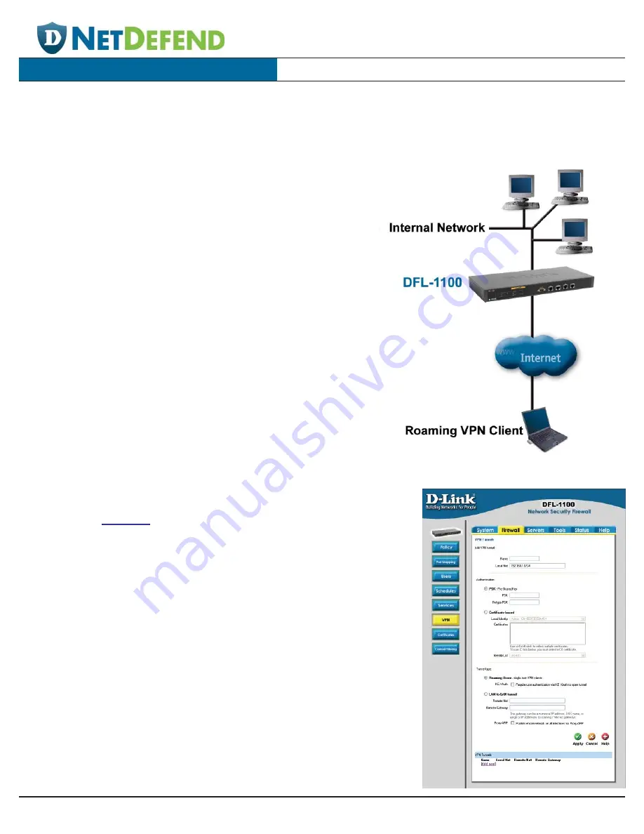
The VPN configuration screen can be found by going to the Firewall tab and selecting the VPN button.

Creating a Roaming Users VPN Tunnel

1. Click on the 

Add new

 link.

2. Enter a name for the new tunnel in the name field. The name can

contain numbers (0-9), upper and lower case letters (A-Z, a-z),
dash (-), or underscore (_).

3. In the Local Net field, enter the local network that your roaming

VPN clients will be connecting to.

4. Choose the authentication type, either PSK (Pre-shared Key) or

Certificate-based. If you select PSK, be sure the clients use exactly
the same PSK.

5. Select Roaming Users as the Tunnel Type.

6. Click Apply to apply the settings or click Cancel to disregard the

changes.

IPSec VPN Between a Client and an
Internal Network

Users can connect to the main office internal network from any Internet
connection. Communication between the client and the internal
network takes place in an encrypted VPN tunnel that connects the
DFL-1100 and the roaming users across the Internet. The client can
connect to an internal network or the DMZ network.

Summary of Contents for DFL-1100 - Security Appliance

Page 1: ...g Manual Power Cord System Requirements Computer with an Ethernet adapter and a Windows Mac or Unix based operating system Internet Explorer or Netscape Navigator version 6 0 or above with JavaScript enabled 2004 D Link Systems Inc All rights reserved Trademarks or registered trademarks are the property of their respective holders Software and specifications subject to change without notice DFL 11...

Page 2: ...Console Direct connection to your computer s serial port using an RS 232 cable for firewall configuration The console settings are Bits per second 9600 Data bits 8 Parity None Stop bits 1 WAN Attaches to your external router DSL modem or cable modem LAN Connects to your internal network DMZ Connects to internal servers that will be visible from the Internet FTP SNMP HTTP and DNS ETH4 Sync Can be u...

Page 3: ...the other end of the Ethernet cable to the WAN port on the front panel of the DFL 1100 5 Power on the broadband modem It may take a few seconds for your modem to initialize but then the WAN port LED should illuminate to indicate a proper connection 6 Connect an Ethernet cable to the LAN port on the front panel of the DFL 1100 Connect the other end of the Ethernet cable to your network hub or switc...

Page 4: ...f the DFL 1100 in the address field and press enter If using the DFL 1100 s default IP address you would enter https 192 168 1 1 Note Include the s at the end of https to ensure a secure connection Once you ve connected to the DFL 1100 the Setup Wizard automatically begins It is recommended that you connect to the DFL 1100 using secure HTTP only To do so select Secure HTTP HTTPS only and click Nex...

Page 5: ... daylight savings time settings Click Next to continue Step 3 Configure WAN interface Select the type of Internet connection that you have If you are unsure of which to select please contact your Internet Service Provider Click Next to continue If you selected DHCP proceed to step 4 on page 8 ...

Page 6: ...st complete all of the fields except for Secondary DNS Server Click Next and continue to Step 4 on page 8 Step 3 PPPoE If you selected PPPoE you will have to fill out the user name and password provided by your Internet Service Provider Leave the PPPoE Service Name field blank unless instructed by your Internet Service Provider Click Next and continue to Step 4 on page 8 ...

Page 7: ...ame and password and then retype the password This information is provided to you from your Internet Service Provider Click Next to continue Step 3 PPTP If you selected PPTP you will need to specify both the tunnel parameters and the physical interface parameters Click Next and continue to Step 4 on page 8 ...

Page 8: ...l LAN clients configured for DHCP The IP range defines the beginning and ending addresses to provide the clients Be sure the IP range does not conflict with any manually configured network devices or the IP address of the DFL 1100 Step 5 Configure helper servers Time Servers When enabled the firewall time will be synchronized with the NTP servers entered here Syslog Servers When enabled the DFL 11...

Page 9: ...ndicating that the unit is restarting After you ve configured the unit you will need to reconnect to the web browser interface Type in https 192 168 1 1 Be sure to include the s in https Type in the admin username and the password that you defined during the Setup Wizard ...

Page 10: ...10 The Setup Wizard DFL 1100 Installation Guide Installation is complete You should see the System Status screen after reconnecting to the DFL 1100 ...

Page 11: ...anges window Once the changes are activated the admin account must login within the timeout period configured on this page If not the changes will be discarded and the previous configuration will be used Once you ve set the desired timeout period click the Activate Changes button to activate the configuration changes The DFL 1100 will save the configuration reload it and the new changes will take ...

Page 12: ...ing the Setup Wizard determines whether you can access the DFL 1100 via HTTP and HTTPS or only via HTTPS Additional interfaces can be configured for administrative access by selecting the appropriate interface WAN DMZ or ETH4 Management web GUI ports These are the HTTP and HTTPS ports being utilized by the DFL 1100 for web based configuration The default settings are the standard port 80 for HTTP ...

Page 13: ...eb based configuration Configuration via HTTP and HTTPS or only HTTPS can also be configured Read Only If enabled allows users to view but not modify the DFL 1100 configuration from the specified interface Viewing via HTTP and HTTPS or only HTTP can also be configured Note User settings and interface settings limit what a user can do So if a full admin user logs on via an interface configured with...

Page 14: ...ernet connection uses a Static IPAddress this information is provided to you by your Internet Service Provider All fields are mandatory except for the Secondary DNS Server IP Address The IP Address of the WAN interface This is the address that is used to ping the firewall remotely control it and as a source address for dynamically translated connections Subnet Mask Network and subnet identifier Ga...

Page 15: ...enter any other information your Internet Service Provider ISP requires Username The login or username supplied by your ISP Password The password associated with the login or username Service Name Only use this option if required by your ISP They will provide you the Service Name to enter Primary and Secondary DNS Server The IP addresses of your DNS servers These are optional and often provided by...

Page 16: ...lity value is used by the PC running the Syslog Daemon to sort messages Local0 is the default value as this is the usual value assigned to a firewall 4 Click Apply to apply the settings or click Cancel to disregard the changes To Enable Audit Logging To start auditing all firewall traffic simply place a checkmark in the Enable audit logging box Be sure to click Apply to apply the setting or click ...

Page 17: ...e appropriate radio button 3 Click Apply to apply the settings or click Cancel to disregard the changes Using NTP to Sync Time 1 Enable synchronization by checking the Enable NTP box 2 Enter the server IP address or server name with which you want to synchronize 3 Click Apply to apply the settings or click Cancel to disregard the changes Setting the Time and Date Manually 1 Place a checkmark in th...

Page 18: ... Nets Specifies the sender span of IP addresses to be compared to the received packet Leave this blank to match everything Source Users Groups Here you can specify that a username group or any authenticated user must be the source for the action to occur A list of usernames can be entered separated by a comma or write Any to represent any authenticated user If it s left blank there is no need for ...

Page 19: ...Source Nets Specifies the sender span of IP addresses to be compared to the received packet Leave this blank to match everything Source Users Groups Here you can specify that a username group or any authenticated user must be the source for the action to occur A list of usernames can be entered separated by a comma or write Any to represent any authenticated user If it s left blank there is no nee...

Page 20: ... clients will be connecting to 4 Choose the authentication type either PSK Pre shared Key or Certificate based If you select PSK be sure the clients use exactly the same PSK 5 Select Roaming Users as the Tunnel Type 6 Click Apply to apply the settings or click Cancel to disregard the changes IPSec VPN Between a Client and an Internal Network Users can connect to the main office internal network fr...

Page 21: ...ting a LAN to LAN VPN Tunnel Note These steps should be performed on both DFL 1100 units 1 Click on the Add new link 2 Enter a name for the new tunnel in the name field The name can contain numbers 0 9 upper and lower case letters A Z a z dash or underscore _ 3 In the Local Net field enter the local network that the LAN to LAN tunnel will be using 4 Choose the authentication type either PSK Pre sh...

Page 22: ...L 1100 is fully configured you can save the configuration file to a local drive The configuration can be restored from the configuration file on the local drive at any time To Export the Configuration File 1 Click on the Download Configuration button 2 Choose a destination location for saving the configuration file The administrator may rename the file if desired To Load a Previously Saved Configu...

Page 23: ...restart is the same as starting up after the unit has been powered off 2 Click on the Restart Unit button and the unit will restart Reset System Settings to Factory Defaults If you reset the system settings to the factory defaults you will lose all changes that you ve made to the DFL 1100 configuration The system reset will also revert to the original firmware version if the unit s firmware has be...

Page 24: ...t D Link Technical Support through our website or by phone Tech Support for customers within the United States D Link Technical Support over the Telephone 877 453 5465 6am 6pm PST Mon Fri D Link Technical Support over the Internet http support dlink com email support dlink com Tech Support for customers within Canada D Link Technical Support over the Telephone 800 361 5265 Monday to Friday 8 30am ...

Reviews: