background image


5


LED Indicators 


LED 

stands for 

L

ight-

E

mitting 

D

iode

.   

The front panel LEDs provides instant status feedback and simplifies 
monitoring and troubleshooting tasks. 


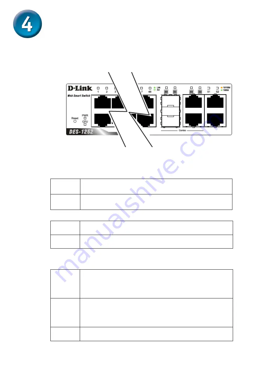
LED indicators of the Switch


„


Power LEDs 

On 

When the Power LED light is on, the Switch is 
receiving power. 

Off 

When the Power LED light is off, the power cord is 
not or improperly connected. 

„


CPU LEDs ( Management Indicator) 

Blinking  When the CPU is working, the CPU LED is blinking.

Off 

The CPU is idle. 

„


Ports 1 ~ 48 Status LEDs 

Link/Act 

On 

When the Link/Act LED light is on, the respective 
port is successfully connected to an Ethernet 
network. 

Blinking  When the Link/Act LED is blinking, the port is 

transmitting or receiving data on the Ethernet 
network. 

Off No 

link. 


Summary of Contents for DES-1252 - Web Smart Switch

Page 1: ...tems included with your DES 1252 purchase If any of the above items are missing please contact your reseller 2006 D Link Systems Inc All rights reserved Trademarks or registered trademarks are the property of their respective holders Software and specifications subject to change without notice DES 1252 D Link 48 Port 10 100Mbps Smart Switch with 4 10 100 1000Base T ports and 2 Combo SFP CD ROM con...

Page 2: ...generators such as motors vibration dust and direct exposure to sunlight C Leave at least 10cm about 4 inches of space at the front and rear of the switch for ventilation D Visually inspect the DC power jack and make sure that it is fully secured to the power adapter E Install the DES 1252 on a sturdy level surface that can support its weight or in an EIA standard size equipment rack F When instal...

Page 3: ...nd 2 Combo SFPs It runs full half duplex transfer mode for 10 100Mbps and full duplex transfer mode for 1000Mbps Each port on the DES 1252 supports Auto MDI MDI X Auto MDI MDI X is a feature that enables the switch to auto sense what kind of cable is used on a port straight or crossover This allows any type of cables to be used with the switch regardless of what device is being connected AC Power ...

Page 4: ...48 ports can operate in half and full duplex modes 10 100 1000 BASE T Mini GBIC Combo Ports Option Port 49 50 The Switch is also equipped with two combo 10 100 1000 Base T Mini GBIC ports supporting optional 100BASE FX or 1000BASE SX LX Mini GBIC modules for fiber uplinks 10 100 1000 BASE T Twisted Pair Ports Port 51 52 Finally there are 2 Gigabit twisted pair ports that are auto negotiable 10 100...

Page 5: ...g power Off When the Power LED light is off the power cord is not or improperly connected CPU LEDs Management Indicator Blinking When the CPU is working the CPU LED is blinking Off The CPU is idle Ports 1 48 Status LEDs Link Act On When the Link Act LED light is on the respective port is successfully connected to an Ethernet network Blinking When the Link Act LED is blinking the port is transmitti...

Page 6: ...ct On When the respective combo port is connected to a network the Link Act LED light is on Blinking When the LED is blinking the respective combo port is transmitting or receiving data on a network Off No link 1000Mbps On When the 1000Mbps LED light s on the respective port is connected to a 1000Mbps Gigabit Ethernet network Off When the respective port is connected to the 100Mbps Fast Ethernet o...

Page 7: ...network Off No link 1000Mbps On When the 1000Mbps LED light is on the respective port is connected to a 1000Mbps Gigabit Ethernet network Off When the respective port is connected to a 10Mbps Ethernet or 100Mbps Fast Ethernet network or no link 100Mbps On When the 100Mbps LED light is on the respective port is connected to a 100Mbps Fast Ethernet network Off When the respective port is connected t...

Page 8: ...ert the Utility CD in the CD Rom Drive 2 From the Start menu on the Windows desktop choose Run 3 In the Run dialog box type D SmartConsole Utility setup exe where D represents the drive letter of your CD ROM your CD Rom drive is located and click OK 4 Follow the on screen instructions to install the utility 5 Upon completion go to Program Files SmartConsole Utility and execute the SmartConsole uti...

Page 9: ...in the same range as the switch For example if the switch has an IP address of 192 168 0 1 the PC should have an IP address of 192 168 0 x where x is a number between 2 and 254 and a subnet mask of 255 255 255 0 Open your web browser and enter http 192 168 0 1 the factory default IP address in the address box Then press Enter The web configuration can also be accessed through the SmartConsole Util...

Page 10: ...igure 5 Click on the setup item that you want to configure The menu contains the following options System Setting Trap Setting Port Setting SNMP Setting Password Access Control 802 1Q VLAN Trunking IGMP Snooping 802 1D Spanning Tree Port Mirroring 802 1p Default Priority Safeguard Engine Broadcast Storm Control 802 1X Setting Static MAC Dynamic Forwarding Table and Statistics Figure 5 Figure 5 Fig...

Page 11: ...u can also find the Tool menu on the main page Figure 6 Click on it and scroll down as shown in Figure 6 and you can see four options Reset Config Backup Restore Firmware Backup Upload and System Reboot Figure 6 ...

Reviews: