background image


15

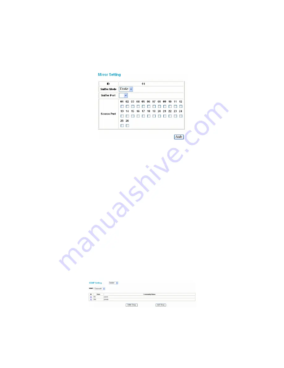
Mirror Setting 

Port Mirroring is a method of monitoring network traffic that forwards a copy of each incoming and/or outgoing packet from one port of a network switch to 
another port where the packet can be studied. It enables the manager to keep close track of switch performance and alter it if necessary. 

Configuring the port mirroring by assigning a source port from which to copy all packets and a sniffer port where those packets will be sent. 

The selection of the sniffer mode is as follows: 

TX (transmit) mode:

 This mode will duplicate the data transmitted from the source port and forward it to the sniffer port. 

RX (receive) mode:

 This mode will duplicate the data sent to the source and forward it to the sniffer port. 

Both (transmit and receive) mode:

 This mode will duplicate both data transmitted from and data sent to the source port, then it will forward it to the sniffer 

port. 


Figure 22. Mirror setting 

SNMP Setting 

Simple Network Management Protocol (SNMP) is an OSI Layer 7 (Application Layer) designed specifically for managing and monitoring network devices. 
SNMP enables network management stations to read and modify the settings of gateways, routers, switches, and other network devices. Use SNMP to 
configure system features for proper operation, monitor performance and detect potential problems in the Switch, switch group or network. 
Managed devices that support SNMP include software (referred to as an agent), which runs locally on the device. A defined set of variables (managed 
objects) is maintained by the SNMP agent and used to manage the device. These objects are defined in a Management Information Base (MIB), which 
provides a standard presentation of the information controlled by the on-board SNMP agent. SNMP defines both the format of the MIB specifications and 
the protocol used to access this information over the network. 
The Switch supports the SNMP versions 1. In SNMP v.1, user authentication is accomplished using 'community strings', which function like passwords. The 
remote user SNMP application and the Switch SNMP must use the same community string. SNMP packets from any station that has not been authenticated 
are ignored (dropped). 
The default community strings for the Switch used for SNMP v.1 management access are:  

public

 - Allows authorized management stations to retrieve MIB objects. 

private

 - Allows authorized management stations to retrieve and modify MIB objects. 

Traps 

Traps are messages that alert network personnel of events that occur on the Switch. The events can be as serious as a reboot (someone accidentally 
turned OFF the Switch), or less serious like a port status change. The Switch generates traps and sends them to the trap recipient (or network manager). 
Typical traps include trap messages for Device boot up, Authentication Failure, Port status change and Abnormal transmit/receive data packet error. 

MIBs 

Management and counter information are stored by the Switch in the Management Information Base (MIB). The Switch uses the standard MIB-II 
Management Information Base module. Consequently, values for MIB objects can be retrieved from any SNMP-based network management software. In 
addition to the standard MIB-II, the Switch also supports its own proprietary enterprise MIB as an extended Management Information Base. The proprietary 
MIB may also be retrieved by specifying the MIB Object Identifier. MIB values can be either read-only or read-write. 

Enabled / Disabled:

 To selecting enable or disable SNMP function on the Switch. 

SNMP Community / Trap:

 To configure the SNMP Community or SNMP Trap configuration. 

Configure SNMP Community: 


Figure 23. SNMP Community Setting 

Add Group:

 To add a SNMP Community group, press 

“Add Group”

 button, the Add SNMP Community configuration window will pop out; fill in the 

community name and assign the community enable read_only or read_write. Press “Apply” button to execute the setting. 

Summary of Contents for DES-1226G

Page 1: ...D Link DES 1226G Web Smart 24 Port 10 100Mbps 2 Port Combo 10 100 1000Mbps Copper SFP Mini GBIC Gigabit Switch Manual Second Edition Building Networks for People RECYCLABLE...

Page 2: ...8 Configuring Setup Setting 13 Port Settings 13 VLAN Settings Virtual Local Area Network 13 Trunk Setting 14 Mirror Setting 15 SNMP Setting 15 Configure SNMP Community 15 Configure SNMP Trap 16 Static...

Page 3: ...ective way of increasing the total network capacity available to users on a LAN If an Ethernet network begins to display symptoms of congestion low throughput slow response times and high rates of col...

Page 4: ...ional copper or fiber Gigabit connections Auto MDI MDI X support on each port Full half duplex transfer mode for 10 100Mbps Fast Ethernet transmission Full duplex transfer mode for Gigabit Ethernet tr...

Page 5: ...a 10 100 1000Mbps Ethernet network Blinking When the LED is blinking the respective port is transferring or receiving data on a 10 100 1000Mbps Ethernet network Off No link 1000Mbps On When the LED l...

Page 6: ...tiable 10 100 1000Mbps and also support auto MDI MDIX crossover detection These two ports can operate in half and full duplex modes SFP Mini GBIC Ports Option Port 25 26 The Switch is equipped with tw...

Page 7: ...device The rubber feet cushion the Switch and protect the Switch case from scratching Figure 4 Attach the adhesive rubber pads to the bottom Rack Mounting The DES 1226G can be mounted in an EIA stand...

Page 8: ...w the on screen instructions to install the utility 5 Upon completion go to Program Files web_management_utility and execute the Web Management utility Figure 1 Figure 7 Web Management Utility The Web...

Page 9: ...he events that occur from the Web Smart Switch in the Monitor List There is a light indicator behind the View Trap button When the light is green it indicates that no trap has been transmitted and whe...

Page 10: ...rocess the password change immediately Figure 11 Password Change Firmware Upgrade When the device has a new function there will be a new firmware to update the device You can use this function to upgr...

Page 11: ...tual LAN Group setting VLAN Trunking Port Mirroring SNMP Static MAC QoS System Setting Device status Login Before you configure this device note that when the Web Smart Switch is configured through an...

Page 12: ...lick on the setup item that you want to configure There are thirteen options Port Settings VLAN Settings Trunk Setting Mirror Setting SNMP Setting Static MAC QoS Setting Device Status Statistic System...

Page 13: ...00M Full 100M Half 10M Full 10M Half Auto and Disable for speed or port disable selections Flow Control This setting determines whether or not the Switch will be handling flow control Set FlowCtrl to...

Page 14: ...two or more devices with a larger bandwidths There are three Trunk groups to be set and there are default ports in each member Checked Enable to use the trunk function select the ports in each member...

Page 15: ...over the network The Switch supports the SNMP versions 1 In SNMP v 1 user authentication is accomplished using community strings which function like passwords The remote user SNMP application and the...

Page 16: ...ss Apply to save change of the SNMP Community Group Figure 196 Modify SNMP Community group Configure SNMP Trap Figure 27 Configure SNMP Trap Setting Trap authentication fail When checked the dialog bo...

Page 17: ...MAC function on the Switch the Switch s auto learning function will be disable except the specific port set in the Disable auto learning excluding uplink port setting and the Switch will forward data...

Page 18: ...Static MAC Setting Add Static MAC rule Press Add Mac button and the Static MAC Setting window will pop out fill in the specific MAC address select the specific port and Vid Press Apply to add rule to...

Page 19: ...e Static MAC rule to forward the packets Figure 35 Add Delete Static MAC QoS Setting To set the Switch QoS base on IEEE 802 1p Figure36 802 1P based QoS Setting Device Status Click on the Status to pr...

Page 20: ...s of the manager where the trap is to be sent Figure 39 Trap Setting System Events Monitoring the system s trap Device Bootup A trap when booting up the system Illegal Login A trap when an incorrect p...

Page 21: ...file Figure 41 Backup Setting Note when restoring a recorded file the current password will not be erased Reset Setting The Factory Reset button helps you to reset the device back to the default setti...

Page 22: ...recommended Fiber module SFP Mini GBIC Fiber module Number of Ports 24 10 100BASE TX Auto MDIX STP ports 2 1000BASE T Auto MDIX STP ports 2 SFP Mini GBIC fiber slot Physical and Environmental AC input...

Page 23: ...ng sold As Is without any warranty whatsoever including without limitation the Limited Warranty as described herein notwithstanding anything stated herein to the contrary Submitting A Claim The custom...

Page 24: ...pyright Statement No part of this publication or documentation accompanying this product may be reproduced in any form or by any means or used to make any derivative such as translation transformation...

Page 25: ...egistration Register online your D Link product at http support dlink com register Product registration is entirely voluntary and failure to complete or return this form will not diminish your warrant...

Page 26: ...nek Aurum ul Walic w 11 PL 00 851 Warszawa Poland TEL 48 0 22 583 92 75 FAX 48 0 22 583 92 76 URL www dlink pl Hungary R k czi t 70 72 HU 1074 Budapest Hungary TEL 36 0 1 461 30 00 FAX 36 0 1 461 30 0...

Page 27: ...site 1 employee 2 9 10 49 50 99 100 499 500 999 1000 or more 3 What network protocol s does your organization use XNS IPX TCP IP DECnet Others_____________________________ 4 What network operating sys...

Page 28: ......

Reviews: