


Introduction
This Quick Installation Guide gives illustrations
for configuring DES-12xx series Fast Ethernet
Switches. The model you have purchased may
appear slightly different from those shown in the
illustrations. Examples in this manual are based
on DES-1218R/DES-1226R switches. However,
the information provided also applies to new
model in the future. For more detailed informa-
tion about the switch, its components, making
network connections and technical specifica-
tions, please refer to the User’s Guide included
with your switch.
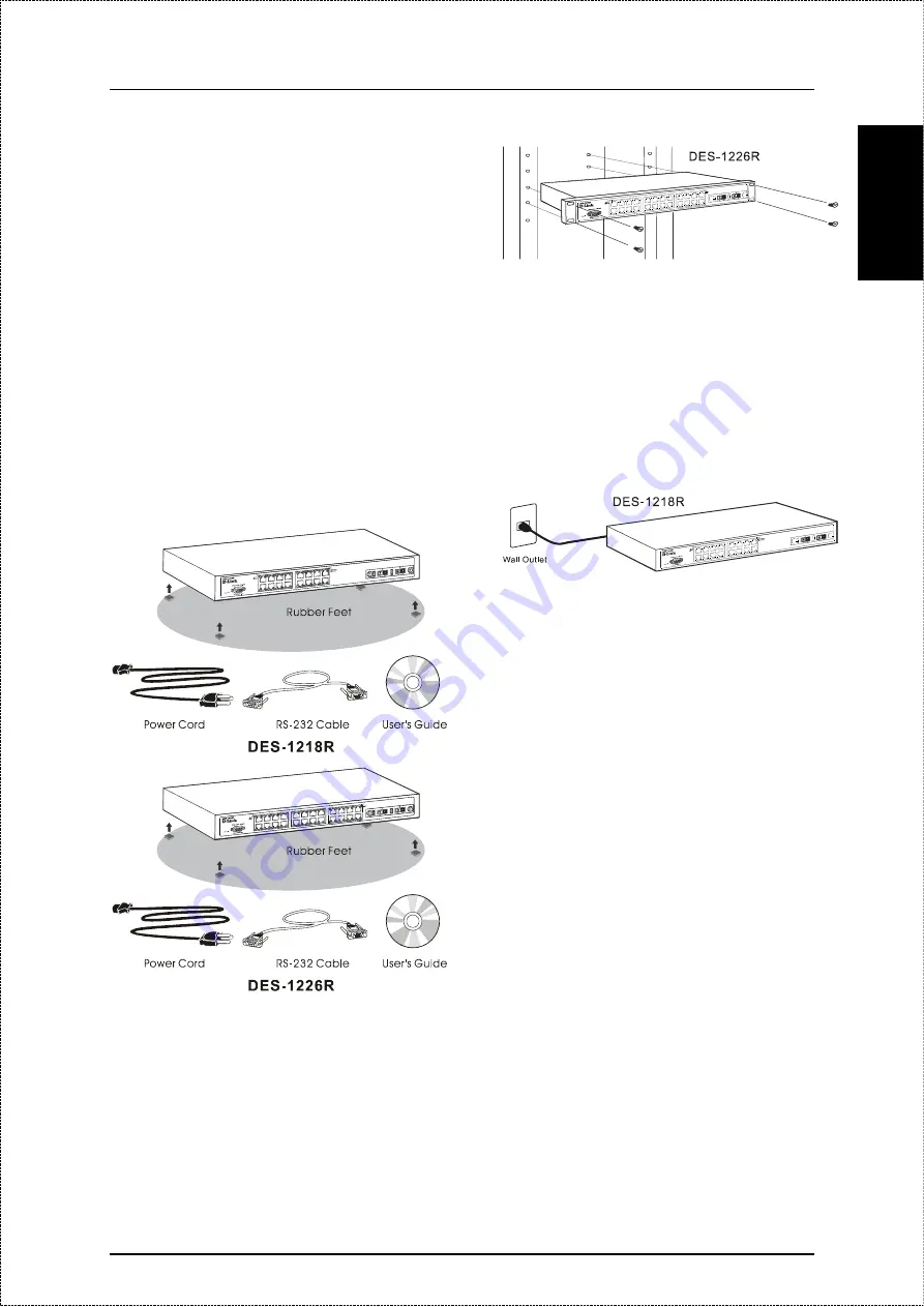
Unpacking
Please make sure the following items are present
and undamaged.
Rack Installation
Attaching the mounting brackets on the switch’s
front panel (one on each side) and secures them
with the screws provided.
Then, use the screws provided with the equip-
ment rack to mount the Switch in the rack.
E
N
G
LIS
H
Plugging in the AC Power Cord
Please connect the AC power cord into an electri-
cal outlet (preferably one that is grounded and
surge protected) and into the rear of the switch.
Once the switch is powered on, you will be able to
immediately see whether the network connection
are valid or not. A valid connection will cause the
Link/Rx
LED on the front panel of the switch to
light up for the corresponding port being con-
nected.
Connecting End Stations
Computers, servers and routers can be connected
to the switch by using normal straight-through
twisted-pair network cables. 10Mbps Ethernet
connections should use Category 3 or better UTP
cabling, while 100Mbps Fast Ethernet connec-
tions should use Category 5 or better UTP or STP
cabling. On the other hand, Gigabit Ethernet
connections will use fiber optic cables. For more
information about cable types, please refer to the
User’s Guide.
Ethernet uses a star topology, so please be atten-
tion that cables should never be connected to
form a loop. Data sent from one computer should
have one, and only one path to the destination
computer.
Uplinking
The switch can be Uplinked to other network de-
vices (hubs, hub stacks, bridges, switches, etc.).
When making uplink connections, make sure
there is only a single connection, and always
connect an Uplink port on one switch to a non-
Uplink port on the other device, as shown in the
diagram below.
The following diagram shows one type of network
connections that can be made to the switch. For
more connection implementations please refer to
the User’s Guide or consult your vendor.
2


