background image

DES-1218/DES-1226 10/100/1000 Mbps Ethernet Switch User’s Guide

3

The modules that can be installed include: the DES-122G 2 port 1000BASE-SX (SC type
connector), DES-122GL 2 port 1000BASE-LX, DES-122GB 2 port GBIC, DES-122T 2
port 1000BASE-T, and DES-122GM 2 port 1000BASE-SX (MT-RJ type connector)
modules.
This stand-alone Switch enables the network to use some of the most demanding
multimedia and imaging applications concurrently with other user applications without
creating bottlenecks. The built-in console interface can be used to configure the Switch’s
settings for Priority Queuing, VLAN, and Port Trunk Groups, Port Monitoring and Port
Speed.

Performance features


IEEE802.3 compliant


IEEE802.3u compliant


IEEE802.3z compliant


IEEE802.3ab compliant


IEEE802.1p Priority Queues


IEEE802.3x flow control in full duplex mode


NWay Auto-negotiation


Full and half-duplex for both 10Mbps and 100Mbps connections. The Gigabit
Ethernet extension module operates at full-duplex only. Full-duplex allows the
switch port to simultaneously transmit and receive data, and only works with
connections to full-duplex capable end stations and switches. Connections to a hub
must take place at half-duplex


Supports single-mode and multi-mode connections


Store and forward switching scheme capability to support rate adaptation and
protocol conversion


Auto-polarity detection and correction of incorrect polarity on the 10/100Mbps TX
ports


Data forwarding rate 14,880 pps per port at 100% of wire-speed for 10Mbps speed


Data forwarding rate 148,810 pps per port at 100% of wire-speed for 100Mbps
speed


Data forwarding rate 1,488,100 pps per port at 100% of wire-speed for 1000Mbps
speed


Data filtering rate eliminates all error packets, runts, etc. at 14,880 pps per port at
100% of wire-speed for 10Mbps speed


Data filtering rate eliminates all error packets, runts, etc. at 148,810 pps per port
at 100% of wire-speed for 100Mbps speed


Data filtering rate eliminates all error packets, runts, etc. at 1,488,100 pps per
port at 100% of wire-speed for 1000Mbps speed


Forwarding 64 to1536 byte frames with correct CRC checksum


Layer 2 switching based on MAC address


Address handling : auto-learning , auto-aging


Address table : Support addresses up to 17K


Buffer size: 8 Megabytes (DES-1218 ) 

10 Megabytes (DES-1226)


Broadcast storm control


Supports 9 Port-based VLAN Groups


Port Trunking


Back pressure in half-duplex

Summary of Contents for DES-1218

Page 1: ...DES 1218 DES1226 10 100 1000Mbps SwitchwithoptionalGigabitmodule User sGuide First Edition June 2000 651ES1218015 Printed In Taiwan RECYCLABLE ...

Page 2: ...h am Geräten befinden sind zu beachten 12 Wird das Gerät über einen längeren Zeitraum nicht benutzt sollten Sie es vom Stromnetz trennen Somit wird im Falle einer Überspannung eine Beschädigung vermieden 13 Durch die Lüftungsöffnungen dürfen niemals Gegenstände oder Flüssigkeiten in das Gerät gelangen Dies könnte einen Brand bzw Elektrischen Schlag auslösen 14 Öffnen Sie niemals das Gerät Das Gerä...

Page 3: ...mory data of Purchaser contained in stored on or integrated with any product returned to D Link pursuant to this warranty Any package returned to D Link without an RMA number will be rejected and shipped back to Purchaser at Purchaser s expense and D Link reserves the right in such a case to levy a reasonable handling charge in addition mailing or shipping costs Software Warranty service for softw...

Page 4: ...HE INSTALLATION MAINTENANCE USE PERFORMANCE FAILURE OR INTERRUPTION OF A D LINK PRODUCT HOWEVER CAUSED AND ON ANY THEORY OF LIABILITY THIS LIMITATION WILL APPLY EVEN IF D LINK HAS BEEN ADVISED OF THE POSSIBILITY OF SUCH DAMAGE IF YOU PURCHASED A D LINK PRODUCT IN THE UNITED STATES SOME STATES DO NOT ALLOW THE LIMITATION OR EXCLUSION OF LIABILITY FOR INCIDENTAL OR CONSEQUENTIAL DAMAGES SO THE ABOVE...

Page 5: ...erference received including interference that may cause undesired operation CE Mark Warning This is a Class A product In a domestic environment this product may cause radio interference in which case the user may be required to take adequate measures Warnung Dies ist ein Produkt der Klasse A Im Wohnbereich kann dieses Produkt Funkstoerungen verursachen In diesem Fall kann vom Benutzer verlangt we...

Page 6: ...122GM 5 2 UNPACKING AND SETUP 6 UNPACKING 6 SETUP 6 DESKTOP OR SHELF INSTALLATION 7 RACK INSTALLATION 7 POWER ON 8 Power Failure 8 3 IDENTIFYING EXTERNAL COMPONENTS 9 FRONT PANEL 9 REAR PANEL 10 SIDE PANELS 11 LED INDICATORS 11 4 CONNECTING THE SWITCH 12 SWITCH TO END NODE 12 SWITCH TO HUB OR SWITCH 13 CONNECTING TO NETWORK BACKBONE OR SERVER 14 5 SWITCH MANAGEMENT 15 LOCAL CONSOLE MANAGEMENT 15 C...

Page 7: ...Port based VLANs 22 VLAN Segmentation 22 VLAN and Trunk Groups 22 7 TECHNICAL SPECIFICATIONS 23 8 CABLES AND CONNECTORS 25 9 CABLE LENGTHS 27 ...

Page 8: ......

Page 9: ...pter 2 Unpacking and Setup Helps you get started with the basic installation of the switch Chapter 3 Identifying External Components Describes the front panel rear panel and LED indicators of the switch Chapter 4 Connecting the Switch Tells how you can connect the Switch to your Ethernet Fast Ethernet network Chapter 5 Switch Management Talks about Local Console Management via the RS 232 DCE conso...

Page 10: ......

Page 11: ... but with a tenfold increase in theoretical throughput over 100Mbps Fast Ethernet and a one hundred fold increase over 10Mbps Ethernet Since it is compatible with all 10Mbps and 100Mbps Ethernet environments Gigabit Ethernet provides a straightforward upgrade without wasting a company s existing investment in hardware software and trained personnel The increased speed and extra bandwidth offered b...

Page 12: ...twork into different collision domains for example making it possible to expand your Fast Ethernet network beyond the 205 meter network diameter limit for 100BASE TX networks Switches supporting both traditional 10Mbps Ethernet and 100Mbps Fast Ethernet are also ideal for bridging between existing 10Mbps networks and new 100Mbps networks Switching LAN technology is a marked improvement over the pr...

Page 13: ... full duplex capable end stations and switches Connections to a hub must take place at half duplex Supports single mode and multi mode connections Store and forward switching scheme capability to support rate adaptation and protocol conversion Auto polarity detection and correction of incorrect polarity on the 10 100Mbps TX ports Data forwarding rate 14 880 pps per port at 100 of wire speed for 10...

Page 14: ...sion Modules 1000BASE SX SC Module DES 122G 1000BASE SX with SC type connector Gigabit Ethernet ports Fully compliant with IEEE802 3z Support Full duplex operation only IEEE 802 3x compliant Flow Control support for full duplex Per port packet buffer 2Mbytes 1000BASE LX SC Module DES 122GL 1000BASE LX with SC type connector Gigabit Ethernet ports Fully compliant with IEEE802 3z Support Full duplex...

Page 15: ... flow control support for half duplex mode Per port packet buffer 2Mbytes 1000BASE SX MT RJ Module DES 122GM 1000BASE SX with MT RJ type connector Gigabit Ethernet ports Fully compliant with IEEE802 3z Support Full duplex operation only IEEE 802 3x compliant Flow Control support for full duplex Per port packet buffer 2Mbytes DES 122GM is not available as of this writing July 2000 ...

Page 16: ...tall the switch on a sturdy level surface that can support at least 3 kg of weight Do not place heavy objects on the switch The power outlet should be within 1 82 meters 6 feet of the switch Visually inspect the power cord and see that it is fully secured to the AC power port Make sure that there is proper heat dissipation from and adequate ventilation around the switch Leave at least 10 cm of spa...

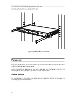
Page 17: ...w enough ventilation space between the switch and any other objects in the vicinity Figure 2 1 DES 1226 Switch installed on a Desktop or Shelf Rack Installation The Switch can be mounted in a standard 19 rack Use the following diagrams to guide you Figure 2 2 Fasten Mounting Brackets to Switch Fasten the mounting brackets to the Switch using the screws provided With the brackets attached securely ...

Page 18: ...AC power cord into the power connector of the switch and the other end into the local power source outlet After the Switch is powered on the LED indicators will momentarily blink This blinking of the LED indicators represents a reset of the system Power Failure As a precaution in the event of a power failure unplug the switch When power is resumed plug the switch back in ...

Page 19: ...nal plug in modules and LED indicators of the Switch Front Panel The front panel of the Switch consists of LED indicators for power and for each port an RS 232 communication port 16 DES 1218 or 24 DES 1226 10 100 Mbps twisted pair ports and a slot for installing an optional 2 port Gigabit Ethernet module DES 1218 Figure 3 1 Front panel view of the DES 1218 ...

Page 20: ... or 100Mbps full or half duplex and flow control MDI X MDI II button for port 1x located between the RS 232 DCE console port and the RJ 45 UTP ports This port can be put in uplink MDI II position by pushing the button in Slot for optional 2 port Gigabit Ethernet module Rear Panel The rear panel contains the AC power connector The AC power connector is a standard three pronged connector that suppor...

Page 21: ...ide Panels the right side panel is pictured on top LED Indicators Power The Power LED will will light green after the switch is powered on to indicate the ready state of the device Link Act Located on the upper left corner of each twisted pair port this LED indicates a valid link steady green and will blink when data is being transmitted via that port connection 10 100 Mbps On the upper right corn...

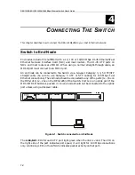
Page 22: ...d to the Switch via a two pair Category 3 4 5 UTP STP straight cable be sure to use Category 5 UTP or STP cabling for 100 Mbps Fast Ethernet connections The end node should be connected to any of the ports 1x 16x on the DES 1218 1x 24x on the DES 1226 of the Switch Port 1x is an uplink port if the MDI X MDI II button is pushed in An end node should not be connected to the uplink port unless using ...

Page 23: ... cable A 100BASE TX hub or switch can be connected to the Switch via a two pair Category 5 UTP STP straight cable If the other switch or hub contains an unused uplink port we suggest connecting the other device s uplink MDI II port to any of the switch s MDI X ports using a normal straight through cable as shown below If the other device does not have an unused uplink port make the connection with...

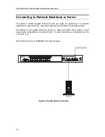
Page 24: ...linking to a network backbone or network server These ports operate at 1000 Mbps in full duplex mode Connection to the Gigabit Ethernet ports are made using fiber optic cable or Cat 5 copper cable depending on the type of port A valid connection is indicated when the Link LED is lit DES 1218 with 2 Port 1000BASE SX Slide in Module Figure 4 3 Gigabit Uplink Connection ...

Page 25: ...t of band management requires connecting a terminal such as a VT 100 or a PC running terminal emulation program such as HyperTerminal which is automatically installed with Microsoft Windows a to the RS 232 DCE console port of the Switch Switch management using the RS 232 DCE console port is called Local Console Management to differentiate it from management done via management platforms such as D ...

Page 26: ...l the available management functions User Interface The command keys are displayed on the bottom of screen move the cursor the correct position to change function setting The command keys are described below Tab move the cursor to the next item Back Space move the cursor to previous item Space toggle select Ctrl r Enter screen refresh Ctrl d all feature settings are reset the default values Ctrl w...

Page 27: ...lf Half duplex mode is only available for 100 Mbps connections in hardware version A2 only IEEE 802 3x Flow Control Enable Disable Note The hardware version A1 or A2 can be found in the lower right hand corner of the management console screen Flow Control Toggles flow control Enable or Disable It is useful during periods of heavy network activity when the Switch s buffers can receive too much traf...

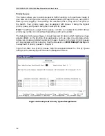
Page 28: ...ou assign to the queues numbers 0 7 represent the IEEE 802 1p priority tag number Do not confuse these settings with port numbers The highest priority queue Queue 3 should reserved for data in which latency can have adverse affects on the function of an application such as video or audio data where latency can produce distorted sounds and images Packets in the lower priority queues will be process...

Page 29: ... in the assigned VLAN A v under the port number indicates the port is in the designated VLAN group Figure 5 3 gives an example of different VLANs assigned to different ports Notice that a port may be a member of more than one VLAN Figure 5 3 Port based VLANs Note In order to use VLAN segmentation in conjunction with port trunk groups you must first set the port trunk group s and then you may confi...

Page 30: ...it rate of 800 Mbps can be achieved Figure 5 4 Example of Port Trunk Group The switch treats all ports in a trunk group as a single port Data transmitted to a specific host destination address will always be transmitted over the same port in a trunk group This allows packets in a data stream to arrive in the same order they were sent A trunk connection can be made with any other switch that mainta...

Page 31: ...Using queues to manage priority tagged data allows you to specify its relative priority to suit the needs of your network There may be circumstances where it would be advantageous to group two or more differently tagged packets into the same queue Generally however it is recommended that the highest priority queue Queue 3 be reserved for data packets with a priority value of 7 Packets that have no...

Page 32: ...r example a packet that is transmitted by a machine on Port 1 that is a member of VLAN 2 If the destination lies on another port found through a normal forwarding table lookup the switch then looks to see if the other port Port 10 is a member of VLAN 2 and can therefore receive VLAN 2 packets If port 10 is not a member of VLAN 2 then the packet will be dropped by the switch and will not reach it s...

Page 33: ...t Ethernet 2000 Mbps full duplex only Topology Star Network Cables 10BASE T 100BASE TX 1000BASE T 1000BASE SX 1000BASE LX UTP Category 3 4 5 100 meters max EIA TIA 568 100 ohm STP 100 meters max UTP Cat 5 100 meters max EIA TIA 568 100 ohm STP 100 meters max UTP Cat 5e 100 meters max UTP Cat 5 100 meters max EIA TIA 568B 100 ohm STP 100 meters max 50 125µm Multimode Fiber optics 550 meters max 62 ...

Page 34: ...26 watts maximum DC Fans 2 built in 40 x 40 mm fans Operating Temperature 32 122 F 0 50 C Storage Temperature 13 131 F 25 55 C Humidity 5 95 non condensing Dimensions DES 1218 DES 1226 441mm x 207mm x 44mm 19 rack mount 1U Weight DES 1218 2 6 Kg DES 1226 2 7 Kg EMI CE Class A C Tick Class A FCC Class A VCCI Class A BSMI Class A Safety UL CUL UL 1950 CSA 950 TUV GS EN 60950 Performance Transmission...

Page 35: ...able pin assignment The following diagrams and tables show the standard RJ 45 receptacle connector and their pin assignments The standard RJ 45 port and connector RJ 45 Pin Assignments Contact MDI X Port MDI II Port 1 RD receive TD transmit 2 RD receive TD transmit 3 TD transmit RD receive 4 Not used Not used 5 Not used Not used 6 TD transmit RD receive 7 Not used Not used 8 Not used Not used The ...

Page 36: ... to create a customized crossover twisted pair cable 1 Leave one end of the cable as is with the RJ 45 connector intact The wiring at just one end of the cable needs to be modified 2 At the other end of the cable connect wires 1 and 2 to contacts 3 and 6 respectively Likewise connect wires 3 and 6 to contacts 1 and 2 Refer to the following diagram Crossover cable for use with MDI X to MDI X and or...

Page 37: ... 50 125µm Multimode Fiber 500 550 Meters 62 5 125µm Multimode Fiber 160 220 Meters 62 5 125µm Multimode Fiber 200 275 Meters 1000BASE LX 50 125µm Multimode Fiber 400 550 Meters 50 125µm Multimode Fiber 500 550 Meters 62 5 125µm Multimode Fiber 500 550 Meters 9µm Single mode Fiber 5 000 Meters 1000BASE T Category 5e UTP Cable Category 5 UTP Cable 100 Meters 100BASE TX Category 5 UTP Cable 100Mbps 1...

Page 38: ......

Page 39: ... me com fateen dlink me com FRANCE D LINK FRANCE Le Florilege 2 Allee de la Fresnerie 78330 Fontenay Le Fleury France TEL 33 1 30238688 FAX 33 1 3023 8689 URL www dlink france fr E MAIL info dlink france fr GERMANY D LINK GERMANY Bachstrae 22 D 65830 Kriftel Germany TEL 49 0 6192 97110 FAX 49 0 6192 9711 11 URL www dlink de BBS 49 0 6192 971199 Analog 49 0 6192 971198 ISDN INFO LINE 00800 7250 000...

Page 40: ... Box 15036 S 167 15 Bromma Sweden TEL 46 0 8564 61900 FAX 46 0 8564 61901 E MAIL info dlink se URL www dlink se TAIWAN D LINK TAIWAN 2F No 119 Pao Chung Road Hsin Tien Taipei Taiwan R O C TEL 886 2 2910 2626 FAX 886 2 2910 1515 URL www dlinktw com tw E MAIL dssqa tsc dlinktw com tw U K D LINK EUROPE D Link House 6 Garland Road Stanmore London HA7 1DP U K TEL 44 20 8235 5555 FAX 44 20 8235 5500 BBS...

Page 41: ... What network protocol s does your organization use XNS IPX TCP IP DECnet Others_______________________________________________________ 4 What network operating system s does your organization use D Link LANsmart Novell NetWare NetWare Lite SCO Unix Xenix PC NFS 3Com 3 Open Banyan Vines DECnet Pathwork Windows NT Windows NTAS Windows 95 Others_______________________________________________________...

Page 42: ......

Reviews: