background image

71

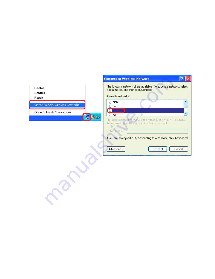
2. The wireless client cannot access the Internet in the

    Infrastructure mode.

Make sure the wireless client is associated and joined with the correct Access

Point.  To check this connection:  

Right-click

 on the 

Local Area Connection icon

in the taskbar> select 

View Available Wireless Networks

.  The 

Connect to

Wireless Network

 screen will appear.  Please make sure you have selected the

correct available network, as shown in the illustrations below.

Troubleshooting

Check that the 

IP Address

 assigned to the wireless adapter is within the

same 

IP Address range

 as the access point and gateway.  

(Since the

DI-764 has an IP Address of 192.168.0.1, wireless adapters must have

an IP Address in the same range, e.g., 192.168.0.x.  Each device must

have a unique IP Address; no two devices may have the same IP

Address. The subnet mask must be the same for all the computers on

the network.)  

To check the 

IP Address

 assigned to the wireless

adapter, 

double-click

 on the 

Local Area Connection icon

 in the

taskbar > select the 

Support tab

 and the 

IP Address

 will be displayed.

(Please refer to 

Checking the IP Address

 in the 

Networking Basics

section of this manual.)

If it is necessary to assign a 

Static IP Address

 to the wireless adapter,

please refer to the appropriate section in 

Networking Basics

.  

If you are

entering a 

DNS Server address

 you must also enter the 

Default

Gateway Address.

  (Remember that if you have a DHCP-capable

router, you will not need to assign a Static IP Address.  See

Networking Basics: Assigning a Static IP Address.

)

default

!

!

Summary of Contents for AirPro DI-764

Page 1: ...2 4 GHz 5 GHz Multimode Manual Building Networks for People AirPro DI 764 Wireless Broadband Router D LINK ...

Page 2: ...ontents 3 Introduction 4 Wireless Basics 6 Getting Started 10 Using the Configuration Menu 12 Networking Basics 41 Troubleshooting 70 Technical Specifications 76 Contacting Technical Support 79 Warranty and Registration 80 ...

Page 3: ...ackage Contents Computer with Windows Macintosh or Linux based operating system with an installed Ethernet adapter Note Using a power supply with a different voltage rating than the one included with the DI 764 will cause damage and void the warranty for this product If any of the above items are missing please contact your reseller System Requirements For Configuration ...

Page 4: ...tiple clients for a seamless Ethernet network connection and shared Internet access At 54Mbps up to 72Mbps in Turbo mode in the 5GHz frequency range and a simultaneous 11 Mbps up to 22 Mbps with D Link AirPlus products in the 2 4GHz frequency range the D Link AirPro DI 764 multimode broadband router delivers the fastest standards based wireless technology in the industry Based on WiFi technology a...

Page 5: ...Mbps at 2 4GHz Wireless range of up to 900 feet Fully 802 11a and 802 11b compatible Supports up to 256 bit WEP Encryption at 2 4GHz and up to 152 bit with Enhanced Dynamic Keying at 5 GHz Less interference with a total of eleven non overlapping channels Utilizes Direct Sequence Spread Spectrum DSSS and Packet Binary Convolutional Code PBCC at 2 4GHz Utilizes Orthogonal Frequency Division Multiple...

Page 6: ...onments and public areas such as airports coffee shops and universities Innovative ways to utilize WLAN technology are helping people to work and communicate Wireless Basics LED LED Activity A steady light indicates a connection to a power source A solid light indicates that the unit is defective A solid light indicates connection on the WAN port This LED blinks during data transmission A solid li...

Page 7: ...based on real time information can significantly improve worker efficiency Low Implementation Costs WLANs Wireless Local Area Networks are easy to set up manage change and relocate Networks that frequently change both physically and logically can benefit from WLANs ease of implementation WLANs can operate in locations where installation of wiring may be impractical Installation Speed and Simplicit...

Page 8: ...specified range of this device you will be able to transfer large files quickly or even watch a movie in MPEG format over your network without noticeable delays This technology works by transmitting high speed digital data over a radio wave utilizing OFDM Orthogonal Frequency Division Multiplexing technology OFDM works by splitting the radio signal into multiple smaller sub signals that are then t...

Page 9: ... AirPro Wireless product s range from 3 90 feet 1 30 meters Position your receiving devices so that the number of walls or ceilings is minimized 2 Be aware of the direct line between routers and computers A wall that is 1 5 feet thick 5 meters at a 45 degree angle appears to be almost 3 feet 1 meter thick At a 2 degree angle it looks over 42 feet 14 meters thick Try to make sure that devices are p...

Page 10: ...resses to the computers on the network please remember that the IP Address for each computer must be in the same IP Address range as all the computers in the network and the Subnet mask must be exactly the same for all the computers in the network For example If the first computer is assigned an IP Address of 192 168 0 2 with a Subnet Mask of 255 255 255 0 then the second computer can be assigned ...

Page 11: ...luded with the DI 764 If you are connecting a desktop computer to your network you can install the D Link AirPro DWL A520 or the DWL 520 wireless PCI adapter into an available PCI slot See the Quick Installation Guide included with the DWL A520 or the DWL 520 If you are connecting a laptop computer to your network install the drivers for the wireless cardbus adapter D Link AirPro DWL A650 into a l...

Page 12: ...below Open the web browser Type in the IP Address of the Access Point Type admin in the User Name field Leave the Password blank Click Next Home Wizard The Home Wizard screen will appear Please refer to the Quick Installation Guide for more information regarding the Setup Wizard http 192 168 0 1 Connect to 192 168 0 1 admin Note if you have changed the default IP Address assigned to the DI 764 mak...

Page 13: ...code for representing English letters as numbers from 0 127 Apply click Apply to save the changes Keys 1 4 input up to 4 WEP keys select the one you wish to use Key Type select HEX or ASCII WEP Encryption select the level of encryption desired 64 128 or 152 bit WEP select Enabled or Disabled Disabled is the default setting Turbo Mode select ON or OFF The default setting is OFF If you enable Turbo ...

Page 14: ... bit WEP select Enabled or Disabled Disabled is the default setting Channel 6 is the default channel for 802 11b All devices on the net work must share the same channel SSID default is the default setting All devices on the network must share the same SSID The SSID may be up to 32 characters long Wireless Settings choose 802 11a or 802 11b Here 802 11b is selected WEP Wired Equivalent Privacy If y...

Page 15: ...atically from their ISP Internet Service Pro vider this is optional but may be required by some ISPs The host name is the device name of the Router the default MAC Address is set to the WAN s physical interface MAC address on the Router copy the MAC address of the Ethernet card installed by your ISP and replace the WAN MAC address with this Ethernet card MAC address It is not recommended that you ...

Page 16: ... Secondary DNS Address Apply select this option to set static IP information provided to you by your ISP input the IP Address provided by your ISP input your Subnet mask All devices in the network must have the same subnet mask input the Gateway address input the address provided by your ISP this is optional click Apply to save the changes ...

Page 17: ...Dynamic PPPoE receive an IP Address automatically from your ISP or User Name your PPPoE username provided by your ISP Password your PPPoE password provided by your ISP Retype Password re enter the PPPoE password Service Name enter the Service Name provided by your ISP optional IP Address this option is only available for Static PPPoE Enter the static IP Address for the PPPoE connection ...

Page 18: ...automatically connect to your ISP after your system is restarted or if the connection is dropped MTU Maximum Transmission Unit 1472 is default you may need to change the MTU to conform with your ISP Maximum Idle Time enter a maximum idle time during which internet connection is maintained during inactivity To disable this feature enter zero or enable Auto reconnect Secondary DNS Address optional P...

Page 19: ... turn your computers on they will automatically load the proper TCP IP settings provided by the DI 764 The DHCP Server will automatically allocate an unused IP address from the IP address pool to the requesting computer You must specify the starting and ending address of the IP address pool DHCP Server select Enabled or Disabled Starting IP Address the starting IP address for the DHCP server s IP ...

Page 20: ... the LAN Local Area Network The DI 764 firewall feature filters out unrecognized packets to protect your LAN network so all computers networked with the DI 764 are invisible to the outside world If you wish you can make some of the LAN computers accessible from the Internet by enabling Virtual Server Depending on the requested service the DI 764 redirects the external service request to the approp...

Page 21: ...e Web Server Private IP 192 168 0 25 Protocol Type TCP Private Port 80 Public Port 80 Schedule always Protocol Type the protocol used for the virtual service Public Port the port number on the WAN Wide Area Network side that will be used to access the virtual service Private Port the port number of the service used by the Private IP computer Schedule The schedule of time when the virtual service w...

Page 22: ...Protocol Type TCP Private Port 21 Public Port 2100 Schedule From 01 00AM to 01 00AM Sat to Sun Using the Configuration Menu Advanced Virtual Server continued Click on this icon to edit the virtual service Click on this icon to delete the virtual service All Internet users who want to access this FTP Server must connect to it from port 2100 This is an example of port redirection and can be useful i...

Page 23: ...to open them for inbound traffic The DI 764 provides some predefined applications in the table on the bottom of the web page Select the application you want to use and enable it Note Only one PC can use each Special Application tunnel Name this is the name referencing the special application Trigger Port this is the port used to trigger the application It can be either a single port or a range of ...

Page 24: ...g restricted web sites click Apply to save changes Apply this is the schedule of time when the IP Filter will be enabled Schedule select the protocol type Protocol Type the single port or port range that will be denied access to the Internet Port Use IP Filters to deny LAN IP addresses from accessing the Internet You can deny specific port numbers or all ports for the specific IP address IP Filter...

Page 25: ...ring that defines a location on the Internet If any part of the URL contains the blocked word the site will not be accessible and the web page will not display select the filter you wish to use in this case URL Blocking was chosen Apply click Apply to save the changes Keywords block URLs which contain keywords listed below Enter the keywords in this space URL Blocking select Enabled or Disabled ...

Page 26: ...ddress from the list of clients that are currently connected to the Broadband Router MAC Filters choose Disable MAC filters allow MAC addresses listed be low or deny MAC addresses listed below Filters select the filter you wish to use in this case MAC filters was chosen Name enter the name here MAC Address enter the MAC Address DHCP Client select a DHCP client from the pull down list click Clone t...

Page 27: ...s to a specific domain such as http and ftp It can also allow computers to access specific sites and deny all other sites select the filter you wish to use in this case Domain Blocking was chosen Disabled Allow Deny enter the Permitted Domains in this field enter the Blocked Domains in this field click Apply to save the changes select Disabled to disable Domain Blocking allows users to access all ...

Page 28: ...ules Firewall Rules contains all network firewall rules pertaining to IP Internet Protocol In the Firewall Rules List at the bottom of the screen the priorities of the rules are from top highest priority to bottom lowest priority Note The DI 764 MAC Address filtering rules have precedence over the Firewall Rules select Always or enter the Time click Apply to save the changes Firewall Rules Name Ac...

Page 29: ...e is useful for gaming purposes Enter the IP address of the internal computer that will be the DMZ host Adding a client to the DMZ Demilitarized Zone may expose your local network to a variety of security risks so only use this option as a last resort DMZ IP Address Apply enable or disable the DMZ The DMZ Demilitarized Zone allows a single computer to be exposed to the internet enter the IP Addres...

Page 30: ...ate best is the default selection Transmit Power full is the default selection Wireless Performance select 802 11a or 802 11b Here 802 11a has been chosen This screen displays the wireless performance features of the Access Point portion of the DI 764 Fragmentation this value should also remain at its default setting of 2346 If you experience a high packet error rate you may slightly in crease you...

Page 31: ...packet error rate you may slightly in crease your Fragmentation value within the range of 256 2346 Setting the Fragmentation value too low may result in poor per formance Wireless Performance Select 802 11a or 802 11b 802 11b is selected here Dis played in this window are the Wireless Performance features for the Access Point portion of the DI 764 DTIM interval Delivery Traffic Indication Message ...

Page 32: ...cy Check block for communication between the DI 764 and roaming wireless adapt ers Make sure to select the appropriate preamble type and click Apply Note High network traffic areas should use the shorter preamble type CRC is a common technique for de tecting data transmission errors Administrator Login Name admin is the default login name for the Admin account User Login Name user is the default l...

Page 33: ...ny Internet IP address to access the Router which could result in a loss of security for your network If you elect to enable Remote Management make sure to enter the IP Address of the remote computer allowed to configure the DI 764 Port For security purposes select a separate port number used to access the Router The following is an example only you may use a different port number Example http x x...

Page 34: ... Save to save the current settings to the local Hard Drive click Browse to find the settings then click Load Save Settings to Local Hard Drive Load Settings from Local Hard Drive Restore to Factory Default Settings click Restore to restore the factory default settings ...

Page 35: ...he link in this screen to find out if there is an updated firmware if so download the new firmware to your hard drive after you have downloaded the new firmware click Browse in this window to locate the firmware update on your hard drive Click Apply to complete the firmware upgrade ...

Page 36: ...ck WAN Ping the WAN IP Address of the DI 764 will not respond to pings Blocking the Ping may provide some extra security from hackers the DI 764 supports VPN Virtual Private Network pass through for both PPTP Point to Point Tunneling Protocol and IPSec IP Security Once VPN pass through is enabled there is no need to open up virtual services Multiple VPN connections can be made through the DI 764 T...

Page 37: ...37 Using the Configuration Menu Status Device Info Device Information This screen displays information about the DI 764 ...

Page 38: ...38 Using the Configuration Menu Status Log View Log Log Settings this screen displays the activity on the DI 764 for advanced features click on Log Settings ...

Page 39: ...ation Menu Status Stats Traffic Statistics displays the receive and transmit packets that are passing through the DI 764 Click on Refresh or Reset for the most recent information displays the wireless clients that are connected to the Access Point function of the DI 764 ...

Page 40: ...40 Using the Configuration Menu Help Help displays the complete Help menu For help at anytime click the Help tab in the Configuration menu ...

Page 41: ...osoft Windows XP Note Please refer to websites such as http www homenethelp com and http www microsoft com windows2000 for information about networking computers using Windows 2000 ME or 98 Go to Start Control Panel Network Connections Select Set up a home or small office network Networking Basics When this screen appears Click Next ...

Page 42: ...uctions in this window Networking Basics Click Next In the following window select the best description of your computer If your computer connects to the internet through a gateway router select the second option as shown Click Next ...

Page 43: ...43 Enter a Computer description and a Computer name optional Networking Basics Click Next Enter a Workgroup name All computers on your network should have the same Workgroup name Click Next ...

Page 44: ... wait while the Network Setup Wizard applies the changes Networking Basics When the changes are complete click Next Please wait while the Network Setup Wizard configures the computer This may take a few minutes ...

Page 45: ...ow select the option that fits your needs In this example Create a Network Setup Disk has been selected You will run this disk on each of the computers on your network Click Next Insert a disk into the Floppy Disk Drive in this case drive A ...

Page 46: ...the information under Here s how in the screen below After you com plete the Network Setup Wizard you will use the Network Setup Disk to run the Network Setup Wizard once on each of the computers on your network To continue click Next ...

Page 47: ...tings will take effect when you restart the computer Click Yes to restart the computer You have completed configuring this computer Next you will need to run the Network Setup Disk on all the other computers on your network After run ning the Network Setup Disk on all your computers your new wireless net work will be ready to use ...

Page 48: ...ndows XP Click Start in the lower left corner of the screen Right click on My Computer Select Properties and click Select the Computer Name Tab in the System Properties window You may enter a Com puter Description if you wish this field is optional To rename the computer and join a domain Click Change ...

Page 49: ...e same Workgroup name Click OK Checking the IP Address in Windows XP The wireless adapter equipped computers in your network must be in the same IP Address range see Getting Started in this manual for a definition of IP Address Range To check on the IP Address of the adapter please do the following Right click on the Local Area Connection icon in the task bar Click on Status ...

Page 50: ... Routers will automatically assign IP Ad dresses to the computers on the network using DHCP Dynamic Host Configura tion Protocol technology If you are using a DHCP capable Gateway Router you will not need to assign Static IP Addresses If you are not using a DHCP capable Gateway Router or you need to assign a Static IP Address please follow these instructions Go to Start Double click on Control Pan...

Page 51: ...51 Networking Basics Assigning a Static IP Address in Windows XP 2000 Double click on Network Connections Double click on Properties Right click on Local Area Connections ...

Page 52: ... that are sequential like 192 168 0 3 and 192 168 0 4 The subnet mask must be the same for all the computers on the network The DNS server address will be supplied by your ISP Internet Service Provider If the DNS Server address is not available from your ISP you may input 192 168 0 1 in this field Click on Internet Protocol TCP IP Click Properties Click OK Enter the IP Address of the Default Gatew...

Page 53: ...own menu Select Manually in the Configure pull down menu Input the Static IP Address the Subnet Mask and the Router IP Address in the appropriate fields Input the Domain Name Server address Your ISP Internet Service Provider will provide the IP address of the DNS Server If the DNS Server address is not avail able from your ISP you may input 192 168 0 1 in this field Click Apply Now ...

Page 54: ...X Go to the Apple Menu and select System Preferences Click on Network Select Built in Ethernet in the Show pull down menu Select Using DHCP in the Configure pull down menu Click Apply Now The IP Address Subnet mask and the Router s IP Address will appear in a few seconds ...

Page 55: ...xx xxx xxx where xxx is the IP Address of the Wireless Router or Access Point A good wireless connection will show four replies from the Wireless Router or Acess Point as shown Go to Start Run type command A window similar to this will appear Type ping xxx xxx xxx xxx where xxx is the IP Address of the Wireless Router or Access Point A good wireless connection will show four replies from the wirel...

Page 56: ... or share a network printer a printer connected to your network through a Gateway Router use the Add Printer Wizard Please follow the directions below First make sure that you have run the Network Setup Wizard on all of the computers on your network On the following pages we will show you these 3 ways to use the Add Printer Wizard 1 Adding a local printer 2 Sharing an network printer 3 Sharing an ...

Page 57: ...uter A printer that is not shared on the network and is connected directly to one computer is called a local printer If you do not need to share your printer on a network follow these directions to add the printer to one computer Go to Start Printers and Faxes Click on Add a printer ...

Page 58: ...to this computer Deselect Automati cally detect and install my Plug and Play printer if it has been selected Click Next Select Use the following port From the pull down menu select the correct port for your printer Most computers use the LPT1 port as shown in the illustration Click Next ...

Page 59: ...xt If the correct driver is not displayed insert the CD or floppy disk that came with your printer and click Have Disk At this screen you can change the name of the printer optional Click Next Select Yes to print a test page A successful printing will confirm that you have chosen the correct driver Click Next ...

Page 60: ...60 Networking Basics Adding a local printer This screen gives you information about your printer Click Finish When the test page has printed Click OK ...

Page 61: ...You have successfully added a local printer Sharing a network printer After you have run the Network Setup Wizard on all the computers on your net work you can run the Add Printer Wizard on all the computers on your network Please follow these directions to use the Add Printer Wizard to share a printer on your network Go to Start Printers and Faxes ...

Page 62: ...62 Networking Basics Sharing a network printer Click on Add a printer Click Next Select Network Printer Click Next ...

Page 63: ...63 Networking Basics Sharing a network printer Select Browse for a printer Click Next Select the printer you would like to share Click Next Click Finish ...

Page 64: ...er installation You have completed adding the printer To share this printer on your network Remember the printer name Run the Add Printer Wizard on all the computers on your network Make sure you have already run the Network Setup Wizard on all the network computers After you run the Add Printer Wizard on all the computers in the network you can share the printer ...

Page 65: ... Server such as the DP 101P Please make sure that you have run the Network Setup Wizard on all the computers on your network To share an LPR printer please follow these directions Go to Start Printers and Faxes Click on Add a Printer The screen to the right will appear Click Next Select Local Printer Click Next ...

Page 66: ...n LPR printer Select Create a new port From the pull down menu select Standard TCP IP Port as shown Click Next Please read the instructions on this screen Click Next Enter the Printer IP Address and the Port Name as shown Click Next ...

Page 67: ...an LPR printer In this screen select Custom Click Settings Enter the Port Name and the Printer Name or IP Address Select LPR Enter a Queue Name if your Print Server Gateway has more than one port you will need a Queue name Click OK ...

Page 68: ...ng driver If the printer driver is already installed do the following Click Have Disk Insert the printer driver disk that came with your printer Select the printer you are adding from the list of Printers Click Finish This screen will show you information about your printer ...

Page 69: ...rs on your network in order to share the printer Click Finish to complete the addition of the printer This screen will display informa tion about your printer Click Next Select Yes to print a test page Click Next Please remember the name of your printer You will need this information when you use the Add Printer Wizard on the other computers on your network You can rename your printer if you choos...

Page 70: ...rs on the network must have a unique IP Address in the same range e g 192 168 0 x Any computers that have identical IP Addresses will not be visible on the network They must all have the same subnet mask e g 255 255 255 0 Do a Ping test to make sure that the DI 764 is responding Go to Start Run Type Command Type ping 192 168 0 1 A successful ping will show four replies Troubleshooting This Chapter...

Page 71: ...st have an IP Address in the same range e g 192 168 0 x Each device must have a unique IP Address no two devices may have the same IP Address The subnet mask must be the same for all the computers on the network To check the IP Address assigned to the wireless adapter double click on the Local Area Connection icon in the taskbar select the Support tab and the IP Address will be displayed Please re...

Page 72: ...network adapters are installed properly You may be using different network adapters than those illustrated here but this procedure will remain the same regardless of the type of network adapters you are using Click Device Manager Select the Hardware Tab ...

Page 73: ...ck on Network Adapters Right click on D Link AirPro DWL A650 Wireless Cardbus Adapter Select Properties to check that the drivers are installed properly Look under Device Status to check that the device is working properly Click OK ...

Page 74: ... drop altogether Try changing the Channel on your Router Access Point and Wireless adapter to a different Channel to avoid interference Keep your product away at least 3 6 feet from electrical devices that generate RF noise like microwaves Monitors electric motors etc 6 Why can t I get a wireless connection To establish a wireless connection while enabling Encryption on the DI 764 you must also en...

Page 75: ... products network together out of the box at the factory default settings To hard reset the D Link AirPro DI 764 to Factory Default Settings please do the following Troubleshooting After the DI 764 reboots this may take a few minutes it will be reset to the factory Default settings Use a paper clip to press the Reset button Hold for about 10 seconds and then release Locate the Reset button on the ...

Page 76: ...er 5V DC 3A Network Management Web Based Interface Network Architecture Supports Infrastructure Mode Diagnostic LED Power 100M Link Act 10M Link Act 11a WLAN 11b WLAN Range Indoors up to 328 feet 100 meters Temperature Operating 0ºC to 40ºC 32ºF to 104ºF Storing 25ºC to 60ºC 77ºF to 140ºF Technical Specifications 1 WAN Port ...

Page 77: ...54 72 Mbps Data Security 64 128 152 bit w dynamic keying Access Control List Antenna Type 5dBi dipole antenna with diversity Power parameter software configurable Available Channels Eight non overlapping channels for North America Frequency Range 5 150 5 350 GHz Modulation Technology Orthogonal Frequency Division Multiplexing OFDM Antenna Type 5dBi dipole antenna with diversity ...

Page 78: ...th America Three non overlapping Frequency Range 2 4 2 4835 GHz Modulation Technology Direct Sequence Spread Spectrum DSSS Packet Binary Convolutional Coding PBCC Modulation Techniques BPSK QPSK 16 QAM 64 QAM 802 11a Specifications continued 11 chip Barker sequence Modulation Techniques Barker 1Mbps 0db Barker 2Mbps 0db PBCC 5 5Mbps 1 5db CCK 11Mbps 8 5db PBCC 11Mbps 4 5db PBCC 22Mbps 8 5db ...

Page 79: ...ustomers can contact D Link technical support through our web site or by phone D Link Technical Support over the Telephone 877 453 5465 24 hours a day seven days a week D Link Technical Support over the Internet http support dlink com When contacting technical support please provide the following information Serial number of the unit Model number or product name Software type and version number Co...

Page 80: ...l specifications for the Software as set forth in the applicable documentation from the date of original retail purchase of the Software for a period of ninety 90 days Warranty Period provided that the Software is properly installed on approved hardware and operated as contemplated in its documentation D Link further warrants that during the Warranty Period the magnetic media on which D Link deliv...

Page 81: ...ion and removal of the product for repair and shipping costs Operational adjustments covered in the operating manual for the product and normal maintenance Damage that occurs in shipment due to act of God failures due to power surge and cosmetic damage Any hardware software firmware or other products or services provided by anyone other than D Link Products that have been purchased from inventory ...

Page 82: ...o radio communication However there is no guarantee that interference will not occur in a particular installation If this equipment does cause harmful interference to radio or television reception which can be determined by turning the equipment off and on the user is encouraged to try to correct the interference by one or more of the following measures Reorient or relocate the receiving antenna I...

Reviews: