background image

86

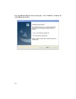
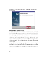
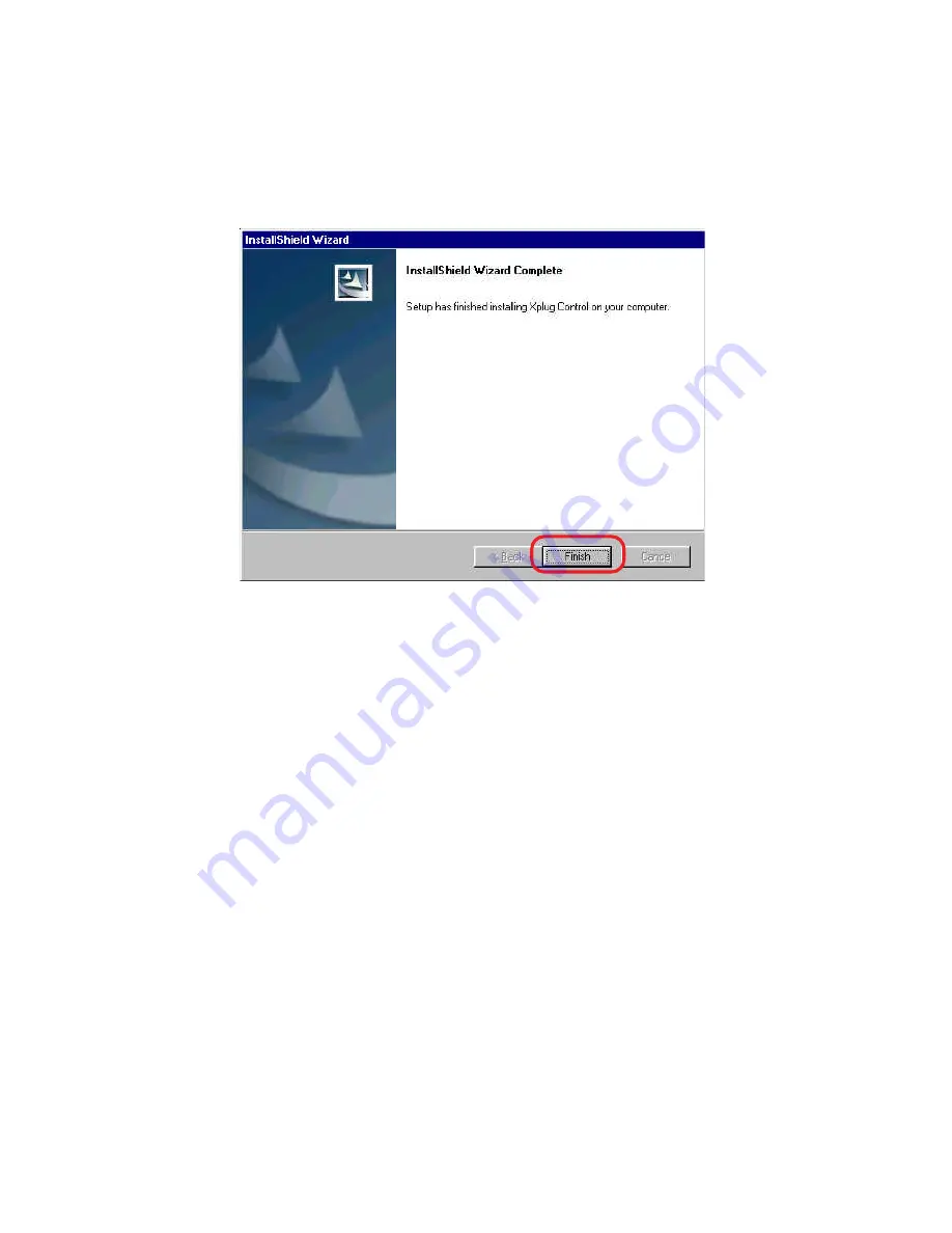
Click 

Finish

 to complete Setup of the Xplug Control Utility program for the

Internet Camera.

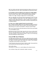
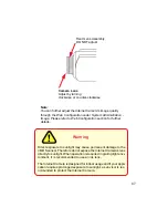
Adjusting the Cameras Focus

The Internet Camera features an exchangeable C/CS-type lens that can be
used for different applications as necessary. It supports rotational focus control
so the lens can be adjusted to focus under normal and stable conditions to
maximize the image quality of the Internet Camera.

To adjust the focus of the lens you will need to turn the lens slowly either
clockwise or counter-clockwise until the desired image appears. DO NOT over-
turn the lens in either direction as it will be out of focus. Unless you want to
substitute the lens DO NOT unscrew more than 1.0mm apart from the Fixed
Lens Assembly.

To help you get the best image quality, keep in mind that while adjusting the
DCS-1000W’s focus you can preview the image quality from your Web browser.

Please refer to the diagram on the next page when adjusting the camera lens.

Summary of Contents for Air DCS-1000W

Page 1: ...DCS 1000 DCS 1000W Manual Version 3 2 10 25 2002 ...

Page 2: ... 10 Using the Internet Camera as a Security System 11 Software Installation 15 IPViewApplication Installation 35 IPView Getting Started 41 Uninstall IPViewApplication 71 Appendix 73 Technical Specifications 89 Contacting Technical Support 91 Warranty and Registration 92 Index 95 ...

Page 3: ...Wireless LAN Wireless Internet Camera only Recommended PC or Notebook to Access the Internet Camera Web Configuration Java Enabled and Compliant Web Browser CPU Pentium II 266 MHz or above Memory Size 32 MB 64 MB recommended VGA card resolution 800x600 or above One Internet Camera Two External Wireless Antennas Wireless Internet Camera only One Installation CD ROM One AC power adapter One Camera S...

Page 4: ...plication environments coupled with many applications such as remote monitoring for a cost effective solution Simple to Use The Internet Camera is a standalone system with built in CPU requiring no special hardware or software such as PC frame grabber cards The Internet Camera supports both ActiveX mode for Internet Explorer and Java mode for Internet Explorer and Netscape Navigator Therefore all ...

Page 5: ...homes offices banks hospitals child care centers amusement parks and other varieties of industrial and public monitoring The Internet Camera can also be used for intruder detection capture still images and video images for archiving and many more applications Connection to External Devices Supporting auxiliary Input Output connectors you can connect the Internet Camera to a variety of external dev...

Page 6: ...when the reset button is pressed once and Power LED begins to flash Factory Reset will be initiated when the reset button is pressed continuously for three seconds or when Power LED begins to light up Release the reset button and the Power LED will begin to flash indicating that the Internet Camera s settings are reverting back to the factory settings When factory reset is completed the Internet C...

Page 7: ...el The I O connectors provide the physical interface to send and receive digital signals to a variety of external alarm devices Please refer to the User s Guide appendix for detailed information Antenna Connector There are two SMA type antenna connectors located at the rear panel of the Internet Camera providing connection for two high sensitivity antenna included with the device Connections conti...

Page 8: ...sage LAN WLAN LED Wireless Internet Camera only The LAN WLAN LED is positioned on the right side of the Internet Camera s lens while facing the Internet Camera It is located to the right of the Power LED Steady orange confirms good connection to the LAN or WLAN Dependent on the data traffic the LED will begin to flash to indicate that the Internet Camera is receiving transceiving from to the LAN o...

Page 9: ...for either LAN or LAN WLAN Wireless Internet Camera only position Please refer to the Physical Description section for detailed information 3 Connect an Ethernet cable Connect an Ethernet cable to the network cable connector located on the Internet Camera s rear panel and attach it to the network 4 Attach the external power supply Attach the external power supply to the DC power input connector lo...

Page 10: ...pports multi level password protection access to the Internet Camera that can be restricted to defined users who have a User Name and User Password which is assigned by the Administrator The administrator can release a public user name and password so that when remote users access the Internet Camera they will have the right to view the image transmitted by the Internet Camera Note When the Intern...

Page 11: ...ace with the DCS family of Cameras Passive components must not exceed 5V 100mA Active components must be self powered by an external power source For the demonstration below a D Link DCS 1000 was purchased from www dlinkshop com the security equipment was purchased from www smarthome com and some cable accessories from a local hardware store Materials DCS 1000 2 Ethernet Cables Ethernet Switch Int...

Page 12: ...V and less then 100mA current to those circuits Distance for passive components is limited by a viewable camera range of about 25 Ft using 26GA wire Active Component Notes A separate power supply is needed for these devices In order to choose the proper PS The total current draw by all the components cannot exceed the Max supplied by the power supply Example Our PIR Motion Detector 17 mA 017A Our ...

Page 13: ...Sending Interval The time between additional sequences of pictures are taken when sensors activated Sending Times The number of times the camera takes additional sequences of pictures based on Sending Interval Trigger I O Enable Output trigger for the specified input trigger Output Time How long the output trigger is activated if the sensor is activated ie How long should the siren ring INPUT TRIG...

Page 14: ...Detector Visonic Ltd Duet Dual Microwave IR Motion Detector Visonic Ltd Bravo 6 Dual PIR Detector DSC Security ProductsAny active security sensor that uses external power and a separate normally closed N C circuit for detection Examples at http www smarthome com secpirmotion html Power and Relay Components ELK Products Inc ELK 924 Single 12V to 120V relay switch DVE Power Supply 12V 1 2A More can ...

Page 15: ...a s IP address in the same segment i e PC 192 168 0 5 Camera 192 168 0 20 for the two devices to communicate For instructions on how to do this please access instructions for installing any of the D Link Broadband Gateway products from support dlink com products The DI 713 or DI 714 are good products to use as an example as their Quick Install Guides are the most up to date Main Menu Image After t...

Page 16: ...on from the Home screen to access the settings required for the Internet Camera There will be several options in the System menu bar to choose from to set your Internet Camera and they are as follows System Image Users Date Time Trigger Information Tools ...

Page 17: ...ystem The System menu contains commands for settings that are required for inputting key details to set up the Internet Camera for operation Click on System in the system administration menu bar and the System screen will appear as illustrated below ...

Page 18: ...fault setting for Admin is blank Null String you need to key in the Admin ID with a maximum length of 12 Printable ASCII characters and enter theAdmin Password with a maximum length of 8 PrintableASCII characters It is highly recommended to set the Admin ID and Admin Password as soon as possible to ensure the highest possible security IP Assignment There are two options to select from the IPAssign...

Page 19: ...g for the wireless communication to take effect Assign Automatically Using If your network is using RARP BOOTP or DHCP server you can click Assign Automatically Using and click on RARP BOOTP or DHCP Under this setting the Internet Camera will automatically assign an IP address from RARP BOOTP or DHCP server Each time the Internet Camera starts up be sure the RARP BOOTP or DHCP server is setup to a...

Page 20: ...nnel from the list provided depending on the regulatory region in which the unit is sold The default setting is channel 11 The default Network Name is a blank space NULL String this default setting will let the Internet Camera connect to any access point under the infrastructure network mode To connect the Internet Camera to a specific access point on the network make sure that you set the ESS ID ...

Page 21: ...cryption code under either Infrastructure mode or Ad hoc mode Encryption WEP Key for Wireless Internet Camera only Wireless network communications are easily intercepted WEP Wired Equivalent Privacy is an encryption method specified by the IEEE 802 11b standard to make any intercepted communications extremely difficult to interpret by unauthorized parties To enable WEP Encryption first decide whic...

Page 22: ...able Therefore to secure the wireless transmission be sure to Enable the Encryption Key by entering the relevant data Note Carefully input the Encryption Code any error setting the code will cause the communication link to fail LED Control The LED control allows you to setup the LED illumination as desired This feature provides the flexibility when surveillance activity is ON There are three optio...

Page 23: ...nstalling ActiveX from the driver CD is included in this manual Refer to the section labeled Software Installation You can open the second port for each Internet Camera from port 81 to Port 85 as illustrated below Internet Camera 1 IP 192 168 0 101 second web port 81 Internet Camera 2 IP 192 168 0 102 second web port 82 Internet Camera 3 IP 192 168 0 103 second web port 83 Internet Camera 4 IP 192...

Page 24: ...less video quality and lower video compression will result in larger files with higher video quality The default setting is Medium Frame Rate Select the frame rate desired with the default setting at Auto for optimal frame rate A setting of Auto will get best results Brightness Control Adjust the brightness level with the default setting of 64 Contrast Control Adjust the contrast level with the de...

Page 25: ...rieved from the Internet Camera System Administration Users The User options menu contains commands to allow the system administrator to assign legal users who are permitted to monitor the Internet Camera from a remote site Click on Users in the system administration menu bar and the Users screen will appear as illustrated below Add User User Name Enter the user name in this field A maximum of 64 ...

Page 26: ...he user you wish to delete from the pull down menu and click on delete icon Important Information Once the administrator has configured the Internet Camera Users any user will be required to enter a login password to access the video image from the Internet Camera The password dialog box is illustrated below System Administration DateTime The DateTime menu contains commands for setting the Interne...

Page 27: ...ver in this field Protocol Two options of NTP or Time are available for your selection to link with the Time Server The default setting is NTP TimeZone The System administrator must select the time zone for the region Please refer to the appendix for the time zone selection table To set the DateTime manually select Set Manually The system administrator must then enter the Date and Time in the resp...

Page 28: ...natively click on the Cancel icon to restore all settings to the values last saved to or retrieved from the Internet Camera System Administration Trigger The Trigger menu contains commands for the I O Trigger connectors providing the physical interface for 2 digital outputs and 2 digital inputs that are used for connecting a diversity of external alarm devices to the Internet Camera such as IR Sen...

Page 29: ...ing sent to the receiver If the setting is at 10 seconds a new e mail will be sent in 10 seconds interval to the receiver Sending Time is the number of times the e mail will be sent to the receiver before it terminates Select Trigger I O Output and enter the setting for the duration of the output device for Output 1 time and Output 2 time in seconds I O Input 2 Trigger Refer to I O Input 1 Trigger...

Page 30: ...pear as illustrated below There are three options to select from the Upload screen FTP Server Time Schedule and Manual Operation FTP Server There are 6 basic settings for your FTP server Host Address The IP Address of the target FTP server Port Number The standard port number for FTP server is Port 21 and it s also the default setting If the FTP server uses a specific port please confirm with the ...

Page 31: ...the Schedule to manage the uploading task In the Schedule option you can set the Day and Time Period option Image Frequency There are two ways to set the image frequency 1 Set Auto 1 2 3 frames per second or 2 Set the time in seconds for every one frame Base File Name Enter the file name to make sure that the images could be saved as the base file name File Since you may not upload only one image ...

Page 32: ...Address System Administration Tools The Tools menu contains commands for restarting the Internet Camera Click on Tools in the system administration menu bar and the Tools screen will appear as illustrated below Reset The Reset command restarts the Internet Camera With Reset you can turn it off and then on again with settings being retained The Reset panel contains the message Do you really want to...

Page 33: ...urning the lens clockwise or counter clockwise to the desired image quality Please refer to the appendix for detailed information regarding Adjusting the Internet Camera Focus and Replacing the Lens View Image ActiveX Mode To view video images from the browser click on View Image ActiveX Mode in the Home screen as illustrated below Location The location of the Internet Camera will be displayed whe...

Page 34: ...permitted to connect to Internet Camera to utilize the output trigger function Please refer to appendix for detailed information Note 2 The Administrator has the authority to allow users to set the output trigger functions through the Upload setting in the System Administration menu bar View Image Java Mode Click on View Image Java Mode from the Home screen to access the video images from the Inte...

Page 35: ...tallation Installation To install the IPView application click on the IPView button to acti vate the installation procedure for the application program Date Time The date time of the Internet Camera will show the date and time which comes either from the time server or from manual settings Insert the CD ROM into the CD ROM drive to initiate the auto run program A menu screen will appear as shown a...

Page 36: ...a prompt will appear requesting the input of the desired language selection Make the desired selection and click on OK to continue The Welcome screen will appear Click on the Next button to proceed with the installation ...

Page 37: ...37 The LicenseAgreement prompt will appear as below Read the details carefully and click on the Yes icon to continue with the installation procedure ...

Page 38: ... is located click on Next to continue If you wish to modify your settings click on Back to return to the previous screens Please wait until one of the two dialog boxes appear select Yes I want to restart my computer now and click on Finish to restart the computer to complete the installation procedure ...

Page 39: ...am for the Internet Camera is automatically installed to Programs Files Directory To start running the IPView click on windows Start Menu Programs IPView IPView Once IPView is executed a Login prompt will appear you must enter the default User Name admin into the respective field and click on OK to log into the application ...

Page 40: ...40 Once logged in the IPView application is executed and the IPView interface will appear as follows in the default List View format ...

Page 41: ...n user interface with detailed procedures for using the application IPView IPView is responsible for the management of preview configuration and searching for each camera It is designed with a user friendly interface for ease of control and navigation as illustrated below List view format ...

Page 42: ...ned only the Administrator has access to the management of IPView applications This procedure should be done as soon as possible to prevent unauthorized usage of the IPView application Once IPView is executed a Login prompt will appear you must enter the default User Name admin into the respective field and click on OK to log into the application To change the User Name and Password select Tools O...

Page 43: ...amera In order to manage cameras in IPView you must first add the cameras to IPView To add a new camera select Camera Add from the IP View An Add Camera dialog box will appear as illustrated below Enter the IP Address of the camera in the specified field and click Add If the IP Address is entered incorrectly a dialog box will appear to notify you of the error Note If you want to add a camera that ...

Page 44: ...era you wish to add and click on Add The Add Camera dialog box will appear once again with the IPAddress entered Click on Add The camera will be automatically be added into the IPView list view format If you are unsure of the IP Address of the camera you can click on Browse the Browse Camera dialog box will appear with a blank screen as illustrated below ...

Page 45: ...ialog box appears make sure to enter the correct User Name and Password Click OK The camera will be added into IPView in list format If the User Name and Password are entered incorrectly the camera will not be added into IPView The above dialog box will appear only if your have already set the User Name and Password during the Web Configuration setting If you forget to highlight the camera you wis...

Page 46: ...ck Yes to delete the camera or click No if you do not wish to delete the camera as illustrated below Make sure to save any changes you have made Note Alternatively you can click the Delete icon as illustrated or use the hot key Del Make sure to save any changes you have made Note 1 You are only able to add one camera at a time Note 2 Alternatively you can click the Add icon as illustrated or use t...

Page 47: ...To change an IP Address for a camera you must first locate the camera by first selecting Camera Add An Add Camera dialog box will appear as illustrated below Click on Browse the Browse Camera dialog box will appear with a blank screen as illustrated below ...

Page 48: ...ed below Highlight the camera you wish to change and click Change IP The Change IP Address dialog box will appear as depicted below Enter the new IP Address the Subnet Mask and the Default gateway into the respective fields and click OK IPView will automatically change the IPAddress Make sure to save any changes you have made ...

Page 49: ... list view format right click on the icon located on the upper left corner of the screen and a case sensitive menu will appear Select List and the viewing image will return to the list view format Note 1 A maximum of 16 cameras are available for viewing with the IPView application Note 2 Alternatively you can click the 1 Camera icon as illustrated or use the hot key Ctrl F3 For 4 Cameras 9 Cameras...

Page 50: ...tate Right or Rotate Left in the menu the video will rotate 90 degrees to the right or left How to take a Snap Shot with the Camera Snap shot To take a snap shot with the camera you must highlight the camera you wish to use from the list view format From the menu bar select Camera Snap shot A Save Image dialog box will appear for you to save the snap shot picture ...

Page 51: ...itive menu will appear Select the Start icon According to the default setting anAVI file will appear in your IPView folder to save the recorded videos Note Please stop recording before you want to change any setting in the internet camera Alternatively you can click the Start icon as illustrated or use the hot key F7 If you are using Windows Media Viewer to view your recorded videos make sure that...

Page 52: ...to the appendix for detailed information The Camera Property dialog box will appear Select the desired options from the tab selections to Configure the camera as shown below General Allows settings for the camera name location and administrator information such as administrator ID and password Please refer to the Web Configuration section under System Administration System for further details ...

Page 53: ...53 IPAssignment There are two options Manually Assign or Assign Automatically Using Please refer to the Web Configuration section System Administration System for further details ...

Page 54: ...me System server is an Internet service that translates domain names into IP addresses Enter at least one DNS IP Address Please refer to the Web Configuration section under System Administration System for further details ...

Page 55: ...or Wireless Internet Camera only Allows for the settings for Connection mode Network name Wireless Channel and WEP key Please see the Web Configuration section under System Administration System for further details ...

Page 56: ...uration section under SystemAdministration System for further details Image Provides the settings for the video image of the camera such as brightness contrast hue resolution compression frame rate and light freq Please refer to the Web Configuration section under System Administration Image for further details ...

Page 57: ...n the Add icon and the Add User dialog box will appear Enter the User Name and Password into the specific field Select the I O Output Control to give users the privilege of accessing the I O Output Control To delete a user select the user and click on the Delete icon Please refer to the Web Configuration section under System Administration Users for further details ...

Page 58: ...ation section under System Administration TimeDate for further details Trigger 1 Contains commands for setting the Input Output Trigger connectors providing the physical interface for 1 digital output and 1 digital input that is used for connecting a diversity of external alarm devices to the camera such as IR Sensor and alarm relay Please refer to the Web Configuration section under System Admini...

Page 59: ... external alarm devices to the camera such as IR Sensor and alarm relay Please refer to the Web Configuration section under System Administration Trigger for further details Information Displays information about the camera such as the model firmware version MAC address and IP address Please refer to the Web Configuration section under System Administration Information for further details ...

Page 60: ...ins commands to reset the camera and update firmware please refer to the appendix for detailed information Please refer to the Web Configuration section under System Administration Tools for further details on reset ...

Page 61: ...e size allocated video images will be recorded into another file automatically Click on By Time in Recording Options if you wish to record to a file for a specified time period Once the time period specified is reached video images will be recorded into a new file automatically Make sure to save any changes you have made to keep the information updated Note If you are using Windows Media Viewer to...

Page 62: ...e period entered Select By Week to indicate specific days to record and the time period Motion Detection This menu sets up motion detection for the camera Click on Motion Detection to enable motion detection Click on Alarm Beep to enable audio notification once motion is detected and Recording Active to start recording once motion is detected The Sensitivity Level can also be adjusted Be sure to A...

Page 63: ...ear in your recording folder that you specified each time the camera is triggered to record In the Camera menu a check mark in front of Enable Motion indicates that the camera is detecting motion and is recording You can manually disable motion detection by clicking on Stop and clicking on Enable Motion which will remove the check mark To re enable motion detection simply click on Enable Motion an...

Page 64: ...navigate the IPView with different selections along with hot key capabilities as follows Menu Bar File File on the menu bar contains New Open Save Save As and Exit for users to create new files open existing files save files and exit the IPView as depicted below ...

Page 65: ...eras 9 Cameras or 16 Cameras mode The View menu bar is pictured below Columns When Columns is launched a dialog box will appear displaying the Column Settings Select the columns that you wish to appear in List View as illustrated below Viewing Format You can view the format in List view The List viewing format allows easy management and control of each camera ...

Page 66: ...d location will be displayed in the list view Note Right click on any camera to bring up a context sensitive menu of actions you can apply to the selected camera Double clicking on the desired camera will bring up the Property dialog box You can click the Refresh icon to update the camera list view ...

Page 67: ...le Motion for Motion Detection The menu bar is illustrated below Enable Function By default the video image is enabled There will be a check next to the Enable command to show that the Enable function is working To disable the real time image select Camera Enable and the real time video image will stop and shutdown Menu Bar Tools Tools on the menu bar allows you to change account information and s...

Page 68: ...e overwritten and replaced by new recorded files Choose Overwrite Time to have video clips recorded in the time frame specified overwritten with new recorded files Choose Overwrite Space to Account Allows you to change your log in name and password overwrite old files with new recorded files once the disk drive reaches the specified drive space ...

Page 69: ... hot key is Ctrl F5 16 Camera view format The hot key is Ctrl F6 Refresh IPView application The hot key is F12 Add a camera The hot key is Shift Ins Delete a camera The hot key is Del Property setting to configure the camera The hot key is F2 Snap shot to capture a single still image The hot key is F5 Options to modify the User Name and Password for IPView The hot key is F10 Start recording video ...

Page 70: ... and Snap shot Enable Motion and Start Stop recordings In View mode format click on the icon located on the upper left corner of the screen and a case sensitive menu will appear as illustrated below These features will be available Enable Rotate Right Rotate Left Snap Shot Enable Motion Start List 1 Camera 4 Cameras 9 Cameras 16 Cameras Previous Page and Next Page ...

Page 71: ...layed like the one below confirming the removal Choose the option that you want and click Next to continue the process or click on Cancel to reject the uninstall process After you click on Next a Confirm Uninstall dialog box will appear Click OK to continue the process Uninstall IPView Application ...

Page 72: ...72 The InstallShield Wizard prompt will appear Click Finish to complete the uninstallation procedure ...

Page 73: ...ion speed will slow down when many users are logged on Q What algorithm is used to compress the digital image A The Internet Camera utilizes JPEG image compression technology providing high quality images JPEG is a standard for image compression and can be applied to various web browser and application software without the need to install extra software Q Can I change the wireless antenna attached...

Page 74: ... Q Can the Internet Camera be setup as a PC cam on the computer A No the Internet Camera is used only on Ethernet and Fast Ethernet network and supported by wireless transmission The D Link DSB C100 DSB C300 DSC 350 or DSC 350F can be used as a PC Camera Webcam Q Can the Internet Camera be connected on the network if it consists of only private IP addresses A The Internet Camera can be connected t...

Page 75: ...rresponds to the first 3 sections of the workstation Therefore the IP address of the Internet Camera must be set from a workstation on the same subnet A3 Other possible problems might be due to the network cable Try replacing your network cable Test the network interface of the product by connecting a local computer to the unit utilizing a standard Crossover hub to hub Cable If the problem is not ...

Page 76: ...web server you may have running on your network A3 The default router setting might be a possible reason Check that the configuration of the router settings allow the Internet Camera to be accessed outside your local LAN Q Why does a series of broad vertical white line appear through out the image A It could be that the CMOS sensor has become overloaded when it has been exposed to bright lights su...

Page 77: ...rer make sure ActiveX has been enabled in the Internet Options menu Alternatively you can use the Java Applet for viewing the required images A2 If you are using Windows XP please make sure that you have downloaded Java and installed it properly A3 Make sure that your web browser supports Java If you are using Internet Explorer or Netscape Navigator with a version number of lower than 4 then you w...

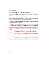
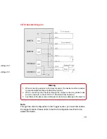
Page 78: ...g external alarm devices and once triggered images will be taken and e mailed The supported transistor output can give a maximum of DC 5V to the externally connected alarm devices and once triggered the current will activate the devices In 11 In 12 In 21 In 22 Out 1 Out 1 Out 2 Out 2 In 11 In 12 is a pair for digital input It works at voltage 5V In 21 In 22 is a pair for digital input It works at ...

Page 79: ...r devices through the Output connector please make sure the maximum current of DC 5V 100mA is strictly observed 3 Any failure of the above two points might cause serious damage to the camera Note Through the Web Configuration in the Trigger section you must first enable the trigger function Please refer to the Web Configuration section for de tailed information voltage 5V voltage 5V ...

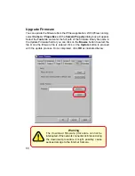
Page 80: ...inary file name in the Update Firmware field or you can click on the Browse button to select the file Once the firmware file is entered click on the Update button to proceed with the update process Once completed click OK as illustrated below Warning The download firmware procedure cannot be interrupted If the network connection is broken during the download procedure it might possibly cause serio...

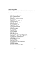
Page 81: ...81 Time Zone Table GMT stands for Greenwich Mean Time which is the global time that all time zones are measured from ...

Page 82: ...82 ...
Page 83: ...b Server table Note the web address of the file location so that you can use it in the next step 2 Configuration From the Web Configuration menu select System and under the Loading ActiveX From input web server location http www web server location com Once the settings are completed you should now be able to access the Internet Camera from the web browser by selecting ActiveX mode Note Set your b...

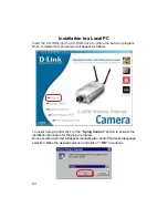
Page 84: ...mpleted a menu screen will appear as follows To install Xplug Control click on the Xplug Control button to activate the installation procedure for the plug in program Once executed a prompt will appear requesting the input of the desired language selection Make the desired selection and click on OK to continue ...

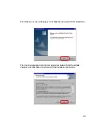
Page 85: ...e Welcome screen will appear Click Next to proceed with the installation The License Agreement prompt will appear as below Read the details carefully and click Yes to continue with the installation procedure ...

Page 86: ...uality of the Internet Camera To adjust the focus of the lens you will need to turn the lens slowly either clockwise or counter clockwise until the desired image appears DO NOT over turn the lens in either direction as it will be out of focus Unless you want to substitute the lens DO NOT unscrew more than 1 0mm apart from the Fixed Lens Assembly To help you get the best image quality keep in mind ...

Page 87: ...ation section for further details Warning Direct exposure to sunlight may cause permanent damage to the CMOS sensor Therefore do not expose the Internet Camera s lens directly to sunlight When operation is required in glaring light envi ronment it is recommended to use an iris lens The Internet Camera is designed for indoor usage and if your appli cation requires prolonged exposure to sunlight a s...

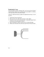
Page 88: ...ructions below to replace the supplied lens with any C or CS type lens 1 Unscrew the Internet Camera lens 2 When using a C lens attach the new lens to a CS C adapter 3 Screw the new lens onto the Internet Camera If appropriate adjust the iris according to the prevailing light conditions 4 Refer to Adjusting the Internet Camera Focus on the previous page 5 Refresh the web browser and monitor the re...

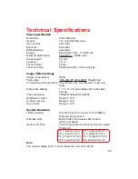
Page 89: ... Low Low Medium High Very High Frame rate setting 1 5 7 15 20 auto depends on the video format Video resolution 160x120 320x240 640x480 Brightness control Range 1 128 Contrast control Range 1 128 Hue control Range 1 128 System Hardware LAN Connector One RJ 45 port to connect to 10 100Mbps Ethernet auto sensed Wireless LAN Built in 802 11b wireless LAN module Wi Fi compliant Generic I O Port Four I...

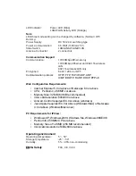
Page 90: ...DP ARP ICMP BOOTP RARP DHCP PPPoE Web Configuration Requirements Internet Explorer 5 0 or above or Netscape 6 0 or above CPU Pentium II 266 MHz or above Memory Size 32 MB 64 MB recommended VGA card resolution 800x600 or above ActiveX Control requires IE4 0 or above windows JavaApplet requires IE4 0 or above Windows Mac or Netscape 4 0 or above Windows Mac Linux PC Requirements for IPView Windows X...

Page 91: ...ustomers can contact D Link technical support through our web site or by phone D Link Technical Support over the Telephone 877 453 5465 24 hours a day seven days a week D Link Technical Support over the Internet http support dlink com When contacting technical support please provide the following information Serial number of the unit Model number or product name Software type and version number Co...

Page 92: ...e price is refunded shall become the property of D Link upon replacement or refund Limited Software Warranty D Link warrants that the software portion of the product Software will substantially conform to D Link s then current functional specifications for the Software as set forth in the applicable documentation from the date of original retail purchase of the Software for a period of ninety 90 d...

Page 93: ... in strict compliance with the foregoing requirements or for which an RMA number is not visible from the outside of the package The product owner agrees to pay D Link s reasonable handling and return shipping charges for any product that is not packaged and shipped in accordance with the foregoing requirements or that is determined by D Link not to be defective or non conforming What Is Not Covere...

Page 94: ...art of this publication or documentation accompanying this Product may be reproduced in any form or by any means or used to make any derivative such as translation transformation or adaptation without permission from D Link Corporation D Link Systems Inc as stipulated by the United States Copyright Act of 1976 Contents are subject to change without prior notice Copyright 2002 by D Link Corporation...

Page 95: ...t Cavity 7 Broad Range of Applications 5 C Change Password 42 Change the IPAddress 43 Columns 63 Connecting the DCS 1000W to the Camera Stand 10 Connection to External Devices 5 Connections 6 Context Sensitive Menu 67 D DC Power Connector 6 Delete a Camera 48 DNS 54 DNS IP Address 19 E Enable Function 65 F Factory Reset 33 Features Benefits 4 format the Camera view 49 Frequently Asked Questions 70...

Page 96: ... the Camera view 49 How to PING Your IP Address 74 How to take a Snap Shot with the Camera 50 I I O Connector 7 75 Installation to a Local PC 81 Internet Camera Installation 71 IP Assignment 53 IPView Icon Description 66 L LAN WLAN LED 8 LED Control 22 LEDS 8 List View 64 M Menu Bar 62 Menu Bar View 63 Menu Bar Camera 65 Menu Bar File 62 Menu Bar Help 65 Menu Bar Tools 65 N Network Cable Connector...

Page 97: ...tration 16 System Requirements 3 T Time Zone Table 78 Trouble Shooting 71 Troubleshooting 71 U Upgrade Firmware 77 Upload 30 V Video specification 86 View Image ActiveX Mode 33 View Image Java Mode 34 Viewing Format 63 W Web Configuration 5 15 Wired and Wireless Network Support 5 Wireless 55 Wireless Interface 19 Wireless Interface 19 X Xplug Control Installation 80 ...

Reviews: