background image

3

• Slots and openings in the cabinet are provided for ventila-

tion. These ensure reliable operation of the product and pro-
tect it from overheating. These openings must not be blocked
or covered. (The openings should never be blocked by plac-
ing the product on bed, sofa,rug, or similar surface. It should
not be placed in a built-in installation such as a bookcase or
rack unless proper ventilation is provided and the manufac-
turer’s instructions have been adhered to.)
For proper ventilation, separate the product from other equip-
ment, which may prevent ventilation and keep a distance of
more than 11-7/8” (30 cm).

• This product should be operated only with the type of power

source indicated on the label. If you are not sure of the type
of power supply to your home, consult your product dealer or
local power company.

• This product is equipped with a three-wire plug. This plug

will fit only into a grounded power outlet. If you are unable to
insert the plug into the outlet, contact your electrician to in-
stall the proper outlet. Do not defeat the safety purpose of
the grounded plug.

• Power-supply cords should be routed so that they are not

likely to be walked on or pinched by items placed upon or
against them. Pay particular attention to cords at doors, plugs,
receptacles, and the point where they exit from the product.

• For added protection of this product during a lightning storm,

or when it is left unattended and unused for long periods of
time, unplug it from the wall outlet and disconnect the cable
system. This will prevent damage to the product due to light-
ning and power line surges.

• Do not overload wall outlets, extension cords, or convenience

receptacles on other equipment as this can result in a risk of
fire or electric shock.

• Never push objects of any kind into this product through open-

ings as they may touch dangerous voltage points or short
out parts that could result in a fire or electric shock.
Never spill liquid of any kind on the product.

• Do not attempt to service this product yourself as opening or

removing covers may expose you to dangerous voltages and
other hazards. Refer all service to qualified service personnel.

• Unplug this product from the wall outlet and refer service to

qualified service personnel under the following conditions:
a) When the power supply cord or plug is damaged.
b) If liquid has been spilled, or objects have fallen on the prod-

uct.

c) If the product has been exposed to rain or water.
d) If the product does not operate normally by following the

operating instructions. Adjust only those controls that are
covered by the Operation Manual, as an improper adjust-
ment of controls may result in damage and will often re-
quire extensive work by a qualified technician to restore
the product to normal operation.

e) If the product has been dropped or damaged in any way.
f ) When the product exhibits a distinct change in perform-

ance - this indicates a need for service.

• When replacement parts are required, be sure the service

technician has used replacement parts specified by the manu-
facturer or with same characteristics as the original part. Un-
authorized substitutions may result in fire, electric shock, or
other hazards.

• Upon completion of any service or repairs to this product,

ask the service technician to perform safety checks to deter-
mine that the product is in proper operating condition.

• The product should be placed more than one foot away from

heat sources such as radiators, heat registers, stoves, and
other products (including amplifiers) that produce heat.

• When connecting other products such as VCR’s, and per-

sonal computers, you should turn off the power of this prod-
uct for protection against electric shock.

• Do not place combustibles behind the cooling fan. For exam-

ple, cloth, paper, matches, aerosol cans or gas lighters that
present special hazards when over heated.

• Do not look into the projection lens while the illumination lamp

is turned on. Exposure of your eyes to the stronglight can
result in impaired eyesight.

• Do not look into the inside of this unit through vents (ventila-

tion holes), etc. Do not look at the illumination lamp directly
by opening the cabinet while the illumination lamp is turned
on. The illumination lamp also contains ultraviolet rays and
the light is so powerful that your eyesight can be impaired.

• Do not drop, hit, or damage the light-source lamp (lamp unit)

in any way. It may cause the light-source lamp to break and
lead to injuries. Do not use a damaged light source lamp. If
the light-source lamp is broken, ask your dealer to repair it.
Fragments from a broken light-source lamp may cause inju-
ries.

• The light-source lamp used in this projector is a high pres-

sure mercury lamp. Be careful when disposing of the light-
source lamp. If anything is unclear, please consult your dealer.

• Do not “ceiling-mount” the projector to a place which tends

to vibrate; otherwise, the attaching fixture of the projector
could be broken by the vibration, possibly causing it to fall or
overturn, which could lead to personal injury.

• Use only the accessory cord designed for this product to pre-

vent shock.
The power supply voltage rating of this product is AC 120 V,
AC 100 V– AC 240 V, the power cord attached conforms to
the following power supply voltage. Use only the power cord
designated by our dealer to ensure Safety and EMC.
When it is used by other power supply voltage, power cable
must be changed.
Ensure that the power cable used for the projector is the cor-
rect type for the AC outlet in your country.
Consult your product dealer.

*DO NOT allow any unqualified person to install the unit.

Be sure to ask your dealer to install the unit (eg.
attaching it to the ceiling) since special technical knowl-
edge and skills are required for installation.
If installation is performed by an unqualified person, it may
cause personal injury or electrical shock.

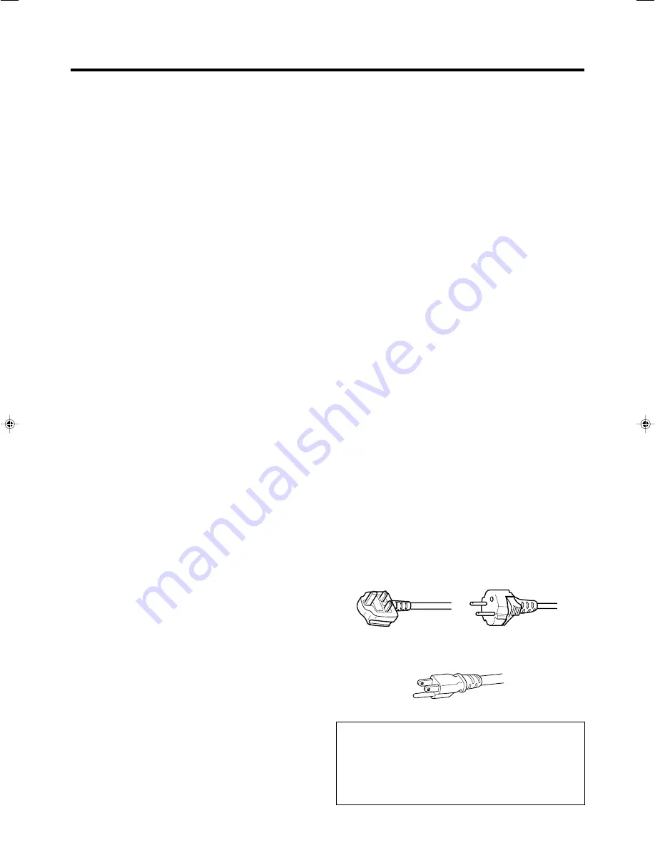
Power cord

For United Kingdom

For European 
continent countries

Power cord

Power supply voltage: AC 120 V

Safety Precaution

Summary of Contents for FDP-DILA3

Page 1: ...FDP DILA3 Serial No Model No NOTICE THIS PROJECTOR HAS BEEN SIGNIFICANTLY MODIFIED AND OPTIMIZED TO PRODUCE VERY HIGH QUALITY IMAGES USING THE FAROUDJA PROCESSOR ANY CHANGES MADE TO THESE SETTINGS CA...

Page 2: ...ive force and uneven surfaces which may cause the product and cart to over turn damaging equipment or causing pos sible injury to the operator PORTABLE CART WARNING symbol provided by RETAC S3126A IMP...

Page 3: ...ance this indicates a need for service When replacement parts are required be sure the service technician has used replacement parts specified by the manu facturer or with same characteristics as the...

Page 4: ...pply If a new main plug has to be fitted then follow the instruction given below POWER CONNECTION United Kingdom only WARNING Do not cut off the main plug from this equipment If the plug fitted is not...

Page 5: ...ked with a neutral detergent Since the cabinet may in time get damaged or deteriorate in condition eg peeling paint Do not wipe with a stiff cloth Do not wipe with force Do not wipe with thinner or be...

Page 6: ...es s ages are dis played 48 Warning Indication 50 S pecifications 51 Dimensions 52 Pin arrangement 53 A c c e s s orie s The following accessories are packed together with this projector Please confir...

Page 7: ...m and Focus Ring Used to manually focus and zoom the image on the screen 1 Control Panel For details See Control Panel on the Projector 2 AC Power Input Terminal This is where the supplied power cord...

Page 8: ...he conversion adapter sold separately for Mac page 22 When computer signals are input the uppermost edge of the image may appear to bow if the sync signal input is composite sync signals or G on sync...

Page 9: ...mp LAMP blinking 1 When the lamp expired Lamp time over 2000hours LAMP light on 1 When time to replace lamp is near Lamp time over 1900hours LAMP and STAND BY blinking 2 When lamp does not light up an...

Page 10: ...page 24 q PC button Use this button to select a device connected to the PC 1 PC 2 or PC 3 terminals page 25 w H KEYSTONE button Use this button to remove the horizontal trapezoidal distor tion of the...

Page 11: ...tter 2 OPERATE button q VIDEO button w PC button e H KEYSTONE button r V KEYSTONE button 3 SCREEN button 4 DIGITAL ZOOM button 5 FREEZE button QUICK ALIGN quick alignment button 7 EXIT button p CURSOR...

Page 12: ...enu When the main menu is displayed pressing this button will cause the menu to disappear page 34 8 ENTER button Press this button to show the next hierarchical menu For example from main menu to sub...

Page 13: ...and old batteries Do not mix different types of batteries as they are differ ent in characteristics Place batteries so they match the polarities indicated on the cartridge Be sure to insert the minus...

Page 14: ...s high in temperature when projecting Please DO NOT use it in the following ways as it may result in fire or malfunction Lay the projector on its side when projecting Project outside the specified ang...

Page 15: ...mounting of the projector is required do it using the embedded three screw holes M6 nuts at the bottom of the projector Precaution for ceiling mount To ceiling mount and adjust the projector special...

Page 16: ...1 56m approx 2 05m Model 60 approx 152 4cm approx 2 37m approx 3 10m Model 80 approx 203 2cm approx 3 18m approx 4 15m Model 100 approx 254 0cm approx 3 99m approx 5 20m Model 120 approx 304 8cm appro...

Page 17: ...ntrol unit are exhausted improper functioning would occur Please replace with new batteries When either the remote control unit or projector alone is connected to the remote cable the connected side w...

Page 18: ...3 Response to DTV format signals DTV format signals 480i 480p 720p 1080i can be input to the Y PB CB PR CR 10 input terminals 10 To use these signals it is required to set the PC2 BNC item in the sub...

Page 19: ...02 68 68 46 43 63 98 79 98 91 15 64 02 75 00 35 00 49 73 60 24 68 68 33 75 33 72 31 47 45 00 44 96 33 75 33 72 28 125 33 750 28 125 27 000 15 734 15 625 15 625 84 13 56 42 59 94 72 81 75 00 85 01 56 2...

Page 20: ...arious Devices B efore connection be s ure to turn off both the projector and device Connecting to Video Devices R ead thoroughly the manual that comes with each video device Connection When connectin...

Page 21: ...r connector Separated cable separately available There are some notebook type computers that do not allow the computer s LCD to work if an external display device is connected With such computers the...

Page 22: ...controlling more than one projector By using the CONTROL terminal more than one projector can be controlled simultaneously by one computer Connect the OUT terminal of the first projector to the IN ter...

Page 23: ...s Against Fire and Electric Shock Since the power requirement of the projector is high please insert the power plug directly into a wall outlet When not using devices remove the power cords from the w...

Page 24: ...ND BY indicator lights up when the power cord is connected 2 Press the OPERATE button on the projector or the OPER ATE button on the remote control unit for one second or more The OPERATE indicator li...

Page 25: ...changes as follows PC1 Projects image from PC1 input terminal on the right hand side of the projector PC2 Projects image from PC2 input terminal on the right hand side of the projector PC3 Projects im...

Page 26: ...immediately remove the Audio vol display Note When the sound volume is displayed on the screen pressing the PRESET button will reset the set value to 0 Power Off 1 Press the OPERATE button on the pro...

Page 27: ...Level Display Level shown is based on selected magnification Enlarging the Image We can zoom up while not changing the size of the projected screen After zooming the position of the image displayed c...

Page 28: ...peration cannot be operated by the projector buttons Please use the remote control unit Press the FREEZE button Picture stills after the FREEZE button is pressed for a few seconds and a message is sho...

Page 29: ...when rein stalling in other rooms etc the trapezoid distortion Keystone has to be removed by adjustments Press V KEYSTONE to adjust in the vertical direction A Vert Keystone display appears on the sc...

Page 30: ...UICK ALIGN appears on the screen and disappears after alignment is complete Notes The Quick Alignment function only works when computer signals are input into the input terminal of either PC1 or PC2 I...

Page 31: ...rmation A ENTER ENTER 12 12 G B R Image adj Set up Logo Options Language Information A GB R 12 15sec ON OFF ON OFF ON 4 3 16 9 5sec OFF ENTER ENTER sRGB MacRGB Color profile Adobe EBU EXIT EXIT Image...

Page 32: ...et Position Tracking Phase Resize Clamp Sync level Position Menu pos Horiz disp pos Vert disp pos Horiz DIST pos Image adj Set up Logo Options Language Information A G B R ENTER ENTER ENTER ENTER Blue...

Page 33: ...uage Information Position Tracking Phase Resize Clamp Sync level Main menu Submenu Image adj Set up Logo Options Language Information A GB R 12 15sec ON OFF ON OFF ON 4 3 16 9 5sec OFF ENTER ENTER ENT...

Page 34: ...menu on the screen When the main menu is displayed press to exit the menu mode Select an item while the main menu hierachy1 is displayed the submenu hierachy 2 corresponding to the item selected will...

Page 35: ...ous one 7 Repeat procedures 2 to 6 to set other items After all adjustments are done Press the MENU button The menu will disappear from the screen The menu item that has been se lected is displayed Th...

Page 36: ...size Set Value 1 1 Panel Aspect Aspect 1 Image adj menu Image adjustment You can adjust the following items on the image adj menu The items displayed differ when Video input or PC input is selected T...

Page 37: ...does not function well select the appropriate decoder accordingly Set Value AUTO NTSC NTSC4 43 PAL SECAM AUTO 6 Logo menu Adjustment item press Adjustment content press Logo disp Sets whether to indic...

Page 38: ...e of image signal input Set Value sRGB MacRGB Adobe EBU Adjustments and Settings Using Menus q Page 2 Adjustment item press Adjustment content press Sleep time min Sets the length of sleep time which...

Page 39: ...tor 0 not being used 1 10 switcher number For details please check with your au thorized dealer Resolution Displays the resolution of the inputted sig nal Horizontal x vertical Some inputted signals c...

Page 40: ...included in your logo 2 Press the MENU button The main menu appears on the screen 3 Select Logo with the CURSOR buttons 4 Press the ENTER or the right CURSOR button The Logo menu appears on the screen...

Page 41: ...z size Vert size Capture start Image adj Set up Logo Options Language Information A 12 12 G B R Capture menu Menu pos Horiz move Vert move Horiz size Vert size Capture start ENTER ENTER Editing and pr...

Page 42: ...ews with a screwdriver When the lamp time exceeds 2000 hours The lamp indicator on the projector blinks Warning and Lamp replacement appears on the screen the word Warning blinks To cancel the message...

Page 43: ...the two claws in first and then ensure that the protruding part found on the reverse side of the cover fits snugly into the hole of the main unit As this protrusion acts as a switch misfitting leads...

Page 44: ...sets and the projector returns to the stand by state STAND BY indicator lights up Resetting the lamp time After replacing with a new lamp reset the Lamp time counter inside the projector When this is...

Page 45: ...t the filter please consult the authorized dealer where you purchased the projector The air inlet filter on the right side cannot be removed Please clean this filter regularly using eg a vacuum cleane...

Page 46: ...ND BY indicator on unplug from the main power outlet close the light source lamp cover correctly and plug on again After the projector goes into the stand by state with the STAND BY indicator on unplu...

Page 47: ...too far from the sen sor Adjust focus with the focus ring of the lens Set the projector at the correct distance Adjust Tracking and Phase on the menu Adjust Brightness on the menu Adjust picture qual...

Page 48: ...output from the connected device The selected input mode input terminal name is shown above the mes sage Please input the image signal The frequency of the input video signal is out of range Please i...

Page 49: ...hours The message can be cleared by pressing the EXIT button However the same message will appear again every one hour Once the projector is turned off it does not turn on again if the accumulated lam...

Page 50: ...dures No 5 Check that nothing is blocking the air inlets and wait until the inside cools down Restart according to the basic operation procedures No 6 Check the ambient temperature If it is normal lea...

Page 51: ...1 line DVI D single 24pin terminal AUDIO 1 line RCApin X 1 Y C VIDEO PC1 PC2 PC3 0 5V rms high impedance CONTROL RS 232C 1 line D sub 9pin x1 External controller REMOTE 1 line stereo mini jack x1 remo...

Page 52: ...Dimensions unit Inches Specifications 6M Depth 10mm An attachment screw should be of a length more than 6mm and less than 10mm D1 Center of lens 181 20 67 5 38 2 298 300 A 52...

Page 53: ...2 Green 3 Blue 4 N C 5 N C 6 GND Red 7 GND Green 8 GND Blue Pin number Signal name 9 N C 10 GND SYNC 11 GND 12 N C 13 H SYNC 14 V SYNC 15 N C Pin number Signal name 1 TMDS data 2 2 TMDS data 2 3 TMDS...

Page 54: ...er set value 1 SP Designates the delimiter for ID Command and Parameter 20h CR Designates the terminal of the data 0Dh is not necessary for Asking command 2 2 Response data format Upon executing the r...

Page 55: ...30h 30h 30h 30h Power on mode 0002 30h 30h 30h 30h Cool down mode 0004 30h 30h 30h 30h Emergency mode Function Command Asking Data type Power on ELSE NumericValue ON OFF Special Data OPERATE U0F X X X...

Page 56: ...ges prepaid Warranty may be void if unit is not returned to Faroudja Service in the original shipping carton Should a product fail to conform to the warranty above then Faroudja shall at Faroudja s so...

Page 57: ...FDP DILA3 THEATER OPTIMIZED PACKAGE Printed in USA 2003 FAROUDJA...

Reviews: