


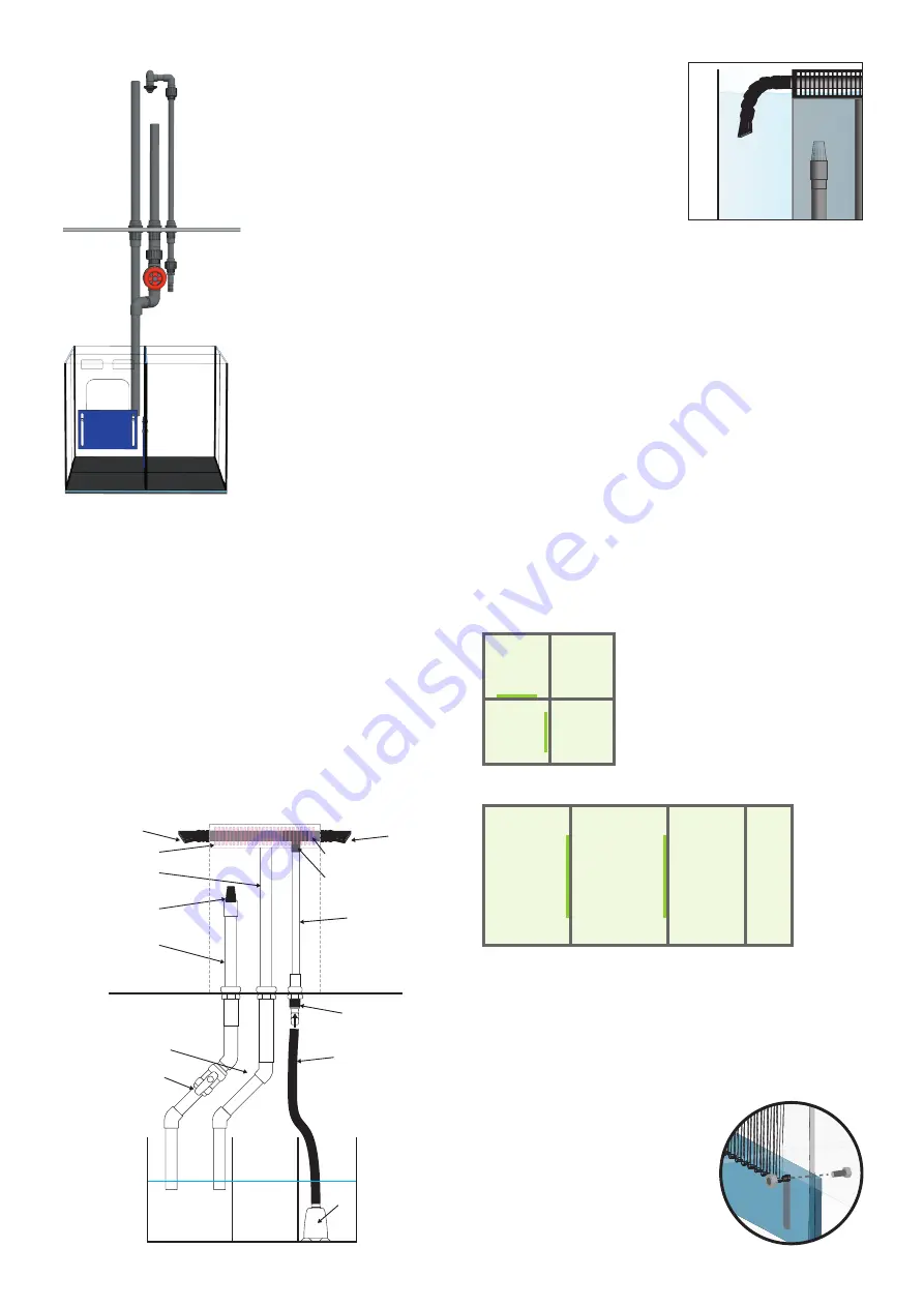
Inlet Assembly 6
Weir Side
Grey T-Piece
Grey Pipe
Flare Nozzle
5
Acrylic
Weir Comb
WEIR
SUMP
7
Flare Nozzle
Outlet Assembly 3
Weir Side
Removable Strainer
Weir Side
Outlet Assembly 1
Weir Side
AQUARIUM BASE
Outlet Assembly 4
Sump Side
Outlet Assembly 2
Sump Side
Flexible Hose (8)
Black PVC
19 / 27mm
Pump
(Not
Supplied)
VIEW FROM FRONT OF AQUARIUM
Return pipe:
line up the
top of the long pipe with
the pre-fitted nozzle
assembly on the weir.
The two halves of the
threaded union should
meet and sit flat against
each other when the
horizontal pipe is level.
The height of the upper
half of the union can be
adjusted by screwing it
into the threaded elbow,
turning clockwise or
anticlockwise to shorten or
lengthen the pipe.
Screw both parts together
with the locking ring.
The pre-assembled
pipework that is fitted
through the weirbox wall
is threaded and can be
removed for cleaning.
Aqua-Pro 900 & 1500 Models
Note that the 900 model is fitted with a single outlet
nozzle and the 1500 is fitted with a twin outlet nozzle.
For these two models only, push the nozzle assembly
into place on the top of the return pipe in the weirbox.
This should be positioned so that the open end(s) are
facing and in line with the holes in the overflow comb.
Finally push the flare nozzle assemblies through the
holes in the sides of the weir comb. It is important that
these are not glued as they will need to be removed
for weir comb maintenance.
VIEW FROM
FRONT OF TANK
5
AQUA-PRO REEF 600 SUMP LAYOUT
Skimmer /
Equipment
Refugium /
Equipment
Top up
reservoir
Return
pump
Skimmer /
Equipment
Refugium /
Equipment
Return
pump
Top up
reservoir
AQUA-PRO REEF 900/1500 SUMP LAYOUT
Please note when
positioning the ends of the
flare nozzles in the aquarium
they must be kept close to
the surface. Failure to do so
may cause excessive water
to be siphoned back into
the sump and cause it to
overflow in the event of a
power outage.
Initial testing of the pipework
Before filling the aquarium, it is best to test that the
pipework and tank connectors do not leak by first
closing the valve on the main overflow pipe and then
filling the overflow box only. Check underneath for any
drips or weeping and, if necessary, tighten up any loose
connections.
If there are no leaks, fully open the valve and continue
with the aquarium set up. Be aware that when opening
the valve, the water used to test the pipe connections
will flow from the weir into the sump.
Sump layout and setup
The glass sump is designed to be large enough to
accommodate most types of equipment and various
methodologies for running a reef aquarium.
Note:
If installing an auto top-up unit, the float should be
installed in the return pump section.
Fitting the adjustable baffles to the sump
The Aqua-Pro 600, 900 and 1500 sumps feature two
adjustable baffles. These allow the water depths in the
first two chambers to be changed for various purposes,
for example, setting the recommended running water
depth of a piece of equipment or creating a deeper
area for a refugium.
Caution: If the baffles are set high,
care must be taken that there is
still enough space in the sump to
handle the drain down volume in
the event of a power outage.
Using the four plastic screws
and nuts provided simply fit the


