background image

8

Manual del Usuario

 / DX series / 

User’s Manual


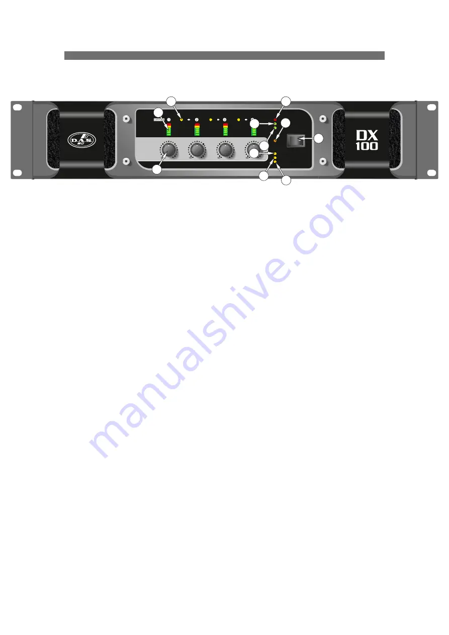
Note: The front panel is common for all models.

1: Analogue level controls: These function in both analogue input and network audio input mode.

2: Signal meters: These will show the level of the respective amplifier's output channel. The red LED in the 
meter will illuminate when the limiter threshold has been reached and limiting is occurring.

3: Link LED: This indicates if the channel is linked to its immediate neighbour. If this is illuminated, the 
attenuation control of the channel to the immediate right will not function as both channels are being fed 
from the left hand channel. Linking is disabled in Network Audio mode and Link LEDs will be extinguished.

4: PROTECTION LED: If a condition exists, either internally or externally, that could cause damage to either 
the  amplifier  or  the  speakers,  the  protection  circuit  will  disengage  the  outputs  and  this  LED  will 
illuminate/flash.


Typical  conditions  that  could  cause  the  protection  to  be  triggered  include  very  high  frequency  or 

subsonic input signals, DC in the inputs, short-circuited outputs, or internal high temperatures.


The protection circuit can affect all channels or a 'channel pair' depending on the type of fault. This is 

indicated by the combination of Protection LED illuminating and a corresponding message on the LCD. In 
this way, it is possible for two channels (a channel pair) to remain functioning even though a fault has caused 
the other channel pair to mute. A channel pair would be 1+2 or 3+4.


Temperature related faults will reset automatically if the unit has cooled sufficiently. Output short circuits 

will require manual reset after clearing the fault (switching off at the mains switch and then on again after a 
few seconds). Short circuits on either channel of a channel pair will only affect that channel pair.

5,6: BRIDGE pair LEDs: The channel pair LED will illuminate if these channels have been switched into 
bridged (mono) mode. See page 11 for details of how to connect your speaker to a bridged channel pair, 
and page 12 for how to enable bridge mode.

7: STBY LED: The 

DX

 amplifiers can be powered down leaving just the input circuitry and Dante network 

audio card (if fitted) active. This LED illuminates when the power amplifier sections are turned OFF.

8: Power Switch: This double pole switch turns the amplifier fully off and isolates it from the mains supply.

FRONT PANEL

PROTECTION

BRIDGE 1+2

BRIDGE 3+4

POWER

LIM

LIM

LIM

LIM

3

3

3

3

6

6

6

6

12

12

12

12

18

18

18

18

24

24

24

24

LINK

LINK

LINK

-12

-12

-12

-12

-6

-6

-6

-6

-20

-20

-20

-20

-4

-4

-4

-4

-2

-2

-2

-2

0dB

0dB

0dB

0dB

ANALOGUE

NETWORK AUDIO

DX SERIES

STBY

-

-

-

-

2

1

6

10

11

5

9

8

3

4

7

Summary of Contents for DX-80

Page 1: ...r el equipo lea la secci n Precauciones de seguridad de este manual Conserveestemanualparafuturasconsultas Before operating the device please read the Safety precautions section of this manual Retaint...

Page 2: ...Electrical Considerations Installation Mechanical Considerations RF Emissions Dynamic Amplifier Performance Measurements Initial Set up and Switching On FRONT PANEL REAR PANEL Maintenance Line Inputs...

Page 3: ...calor tales como radiadores calefactores estufas u otros aparatos que produzcan calor No bloquee las aberturas de ventilaci n e instalar de acuerdo con las instrucciones del fabricante Los ventiladore...

Page 4: ...paraci n en garant a es imprescindible que el producto no haya sido previamente manipulado e incluir una fotocopia de la factura de compra All our products are warrantied against any manufacturing def...

Page 5: ...tus for professional use Part 2 Immunity l EN 50581 2012 Technical documentation for the assessment of electrical and electronic products with respect to the restriction of hazardous substances cumple...

Page 6: ...rmer according to customer requirements Make sure power outlets conform to the power requirements listed on the back of the unit Damage caused by connecting to improper AC voltage is not covered by th...

Page 7: ...lations which use multiple speakers with electronic crossovers or speaker controllers These systems can handle very high transient signals that far exceed their RMS power rating The DX series amplifie...

Page 8: ...is is indicated by the combination of Protection LED illuminating and a corresponding message on the LCD In this way it is possible for two channels a channel pair to remain functioning even though a...

Page 9: ...d source is the four input XLRs 11 NETWORK AUDIO LED This will illuminate when the selected source is the network audio connection FRONT PANEL cont d PROTECTION BRIDGE 1 2 BRIDGE 3 4 POWER LIM LIM LIM...

Page 10: ...perate independently when channels are linked Linking is disabled in Network Audio mode and Link LEDs will be extinguished 7 Input XLR sockets Connect signal inputs to these sockets wired pin 2 hot 3...

Page 11: ...ier is wired to the latest industry recommendations Pin 1 is connected directly to the chassis mains earth If ground loops mains hum are encountered remove the screen connection from the other end of...

Page 12: ...s than 4 Ohms be aware that the current capacity of the speaker cables will need to be increased above the values quoted here Do not connect the inputs outputs to any other voltage source such as a ba...

Page 13: ......

Page 14: ......

Page 15: ...DAS 4 USA DAS Audio Asia PTE LTD 3 Temasek Avenue Centennial Tower 34 36 Singapore 039190 Tel 65 6549 7760 DAS Audio Group S L C Islas Baleares 24 46988 Fuente del Jarro Valencia SPAIN Tel 34 96 134...

Reviews: