
JF-1A Conductivity Sensor
A440-009
Page 47 of 56
FEBRUARY 2009
c)
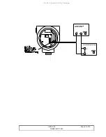
Connect the serial cable to the test jack on the JF-1
Sensor. On the PC press enter and confirm connection
is made by the receipt of a single line of data from the
JF-1 Sensor. (Or turn the unit on add see the turn on
banner being received).
d)
Place the unit in open mode using the “***O”
command followed by the enter key. Verify the unit is
in OPEN MODE by pressing an additional entering
key, the JF-1 will respond with the words “OPEN
MODE”.
e)
Read the current full scale value of the current output
DAC, enter the request “DAF” the unit will return
“DAF=585, where “585”is the current setting, one can
assume the full scale range is 500, note the DAF value
represents a “scaling” factor and will not exactly be
equal to the range.
f)
As we are changing the range to 1000 pS/m full scale
we can make an initial assumption the DAF value will
need to ~ 20% higher than the span of interest, i.e.
DAF=1000*1.2= 1200. This value is temporarily
entered into DAF by sending “DAF=1200”.
g)
To test this value we need only to set conductivity to
our desired full-scale value by sending “Cond=1000”
to the JF-1 unit.
h)
Read the Digital Voltage Meter output that should be
connected across either the 250 or 100-ohm sense
resistor. The voltage should equal 5.00 +/- 0.01 volt
for the 250-ohm resistor, or 2.00 +/- 0.005 volts for the
100-ohm sense. If this is not attained DAF needs to
adjusted, increase the value of DAF if the voltage is
high, decrease the value if the voltage is low. Repeat
Step 6 then Step 7 until the correct voltage (current is
attained).
(Note the unit will not automatically update
the output after a change in DAF is made, the user


