background image

JF-1A CONDUCTIVITY SENSOR 

A440-009 

Page 1 of 56 

FEBRUARY 2009 


D-2 INCORPORATED 


Jet Fuel 1A Conductivity Sensor 

JF-1A 


OPERATION MANUAL 


REVISION 2.1 

FIRMWARE VERSION 2.2 

P/N A441-009 


This manual covers the operational aspects of the D-2 JF-1A Conductivity Sensor.  D-2 
continuously  strives  to  meet  the  full  expectations  of  our  customers  and  we  welcome 
comments  on  the  structure,  content  and  the  ability  of  this  manual  to  answer  your 
questions  regarding  our  product.    If  you  have  any  suggestions  or  comments  please 
contact us at 

[email protected]

.  This document is provided with the understanding that 

future versions of this instrument may have additional commands, and the function of 
the commands shown in this document may vary from the present operation. 


Revision History 
Revision  Description 

Date 

Approved 

2.0 

Incorporated A440-010-FC, Application Note’s 10-006, 10-007 as standard 
elements, remove references to JFWIN, change to Hyperterminal 

15DEC10 

A Fougere 

3.0 

Correct Air/Zero Notations 

28MAR11  A Fougere 


Summary of Contents for JF-1A

Page 1: ...this manual to answer your questions regarding our product If you have any suggestions or comments please contact us at Mail D 2inc com This document is provided with the understanding that future ve...

Page 2: ...ION 5 4 0 THEORY OF OPERATION 6 5 0 D 2 JF 1A SENSOR 7 6 0 MECHANICAL INSTALLATION 8 7 0 ELECTRICAL INSTALLATION 9 8 0 TEST PROCEDURE 15 9 0 SENSOR REMOVAL 17 10 0 SPECIFICATIONS 17 11 0 SERIAL DATA I...

Page 3: ...JF 1A CONDUCTIVITY SENSOR A440 009 Page 3 of 56 FEBRUARY 2009 Appendix A Service Warranty Policy 30...

Page 4: ...ed range of conductivity User configurations and instrument calibration terms are stored in internal non volatile memory The D 2 sensor is continuously internally electronically calibrated Absolute ca...

Page 5: ...ows for its use with industry standard PID Controller Display units combined with additive injector pumps to provide real time control over addition of conductivity enhancing additives during the tran...

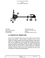
Page 6: ...to the electrodes Conduction through the fuel results in an AC electrical current that is amplified detected and output as either direct serial ASCII data or as a standard 4 20 mA industrial current l...

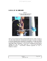
Page 7: ...ined in a sealed approved housing The sensor is designed to be fully intrinsically safe for operation in fuel facilities The back cover allows for direct conduit connection to the meter and offers bot...

Page 8: ...e mounted well away from possible sources of electromagnetic noise such as large pump motors AC power Lines or electrical circuits containing large transient switching currents Note Prior to arc weldi...

Page 9: ...r may be activated The 4 20 mA Loop supply open circuit voltage must be consistent with the Open Circuit Supply needs of the JF 1A at both its minimum and maximum indicating currents The JF 1A has bot...

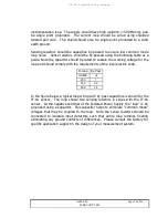
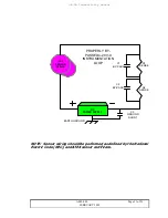
Page 10: ...he loop and should comply with the requirements of the local electric code R Loop By Pass OHMS uF 250 1 350 2 2 500 3 3 In the figure below a typical loop wiring with by pass capacitors is shown for t...

Page 11: ...F 1 SENSOR 4 20 mA DC POWER SUPPLY R1 SENSE R2 SENSE C1 BY PASS C2 BY PASS C3 GROUND SHUNT PROPERLY BY PASSED 4 20 mA INSTRUMENTATION LOOP EARTH GROUND NOTE Sensor wiring should be performed as define...

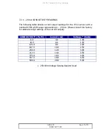
Page 12: ...1A sensor with a nominal 0 500 pS M range representing 4 20 mA Please consult the factory for alternate range settings of the current output CONDUCTIVITY Ps M Current mA Voltage Volts 0 0 4 0 1 00 62...

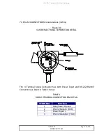
Page 13: ...ure 8A 4 WIRE ELECTRICAL CONNECTION DETAIL 1 2 4 3 3 2 1 3 2 1 The 4 Terminal Screw Connector has both Power Input and RS 232 RS 485 Connections as listed in Table 1 below TABLE 1 SCREW TERMINAL CONNE...

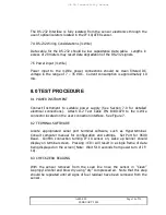
Page 14: ...power supply See Section 7 0 for detailed electrical connections Attach D 2 Test Cable P N B440 079 to the 4 Wire connector located on the user connection interface See Figure 7 8 2 TERMINAL SOFTWARE...

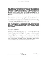
Page 15: ...ble Data is displayed as Conductivity Temperature Compensated Conductivity CR LF Note The sensor is factory calibrated in certified zero conductance fluid The serial port may read a slightly negative...

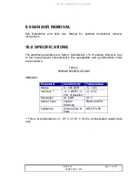
Page 16: ...of reading However due to fuel measurement characteristics the repeatability and reproducibility limits are as follows Table 2 SENSOR SPECIFICATIONS SENSORS Parameter Conductivity Temperature Range 0...

Page 17: ...lectrical adjustments All instrument calibration constants and configurations are stored in internal non volatile memory The unit also has programmable output span range for the 4 20 mA output allowin...

Page 18: ...15 4 Temperature of Fuel in Celsius 23 8 Compensated Conductivity 11 2 CONTINUOUS DATA To have the unit send data continuously without polling the user can send the SC Set Continuous Command The unit...

Page 19: ...67 759354 MT 9 510620E 05 TREF 20 100000 MC 1 280000E 02 N 1 000000 W 30 NREF 1 000000 DAO 375 DAF 500 000000 In the Table Below the definition of each of these constants is given Table 4 OPERATIONAL...

Page 20: ...volatile memory using the E command Note cycling power after changing constants and before storing them in non volatile memory using the E command will result in the unit reverting to the original val...

Page 21: ...l constants To enter the CALIBRATION MODE the C command sent from the OPEN MODE See Open Mode Above After entering CALIBRATION MODE the unit will send the following frame of data when polled using a c...

Page 22: ...electric constant from air to fuel 12 1 SENSOR REMOVAL To remove the probe from the fuel load line please refer to section 9 0 12 2 POWER SENSOR Using D 2 Test Cable P N A440 043 Connect the sensor to...

Page 23: ...held meter or other suitable and industry accepted standardization device Verify reported conductivity from JF 1A and hand held are within acceptable limits 13 0 COMPENSATED OUTPUT The D 2 JF 1A Cond...

Page 24: ...394 506 30 63 190 316 443 570 34 71 214 356 499 641 38 80 240 401 561 721 42 90 270 451 631 811 46 101 304 507 710 913 50 114 342 571 799 1027 The D 2 JF 1A Current Output is base on Compensated Cond...

Page 25: ...F 1A Conductivity Sensor A440 009 Page 25 of 56 FEBRUARY 2009 In the table below 63 and 90 response times are given for each box card setting See Section 10 0 for setting the box car number constant n...

Page 26: ...e JF 1A sensor output can change from scan to scan W has units pS cm scan and can be set from 0 999 W is an effective tool to reduce data output spikes in installations where sudden physical changes o...

Page 27: ...15 2 Cleaning The JF 1A Conductivity Sensor should be cleaned every 6 months of use Fuel additives or particulate may build up on the sensor degrading its performance The sensor can be cleaned using t...

Page 28: ...is connected to JP2 Terminals These are snap out Molex screw terminals which can be removed to assist in wiring Cabling used should be in compliance with the JF 1A Ex examination certificate The 2 wi...

Page 29: ...The supply should have high isolation 500 Mohm and be single point grounded The current loop should be wired using shielded twisted pair wire The shield should also be single point grounded to a solid...

Page 30: ...us freight costs will be borne by the customer All equipment supplied by D 2 that is designed for use under hydrostatic loading has been certified by actual pressure testing prior to shipment The cust...

Page 31: ...e covered If repair is necessary the customer will be contacted and apprised of the additional cost The customer will be charged the standard repair cost which includes repair and calibration In the e...

Page 32: ...o meet the full expectations of our customers and we welcome comments on the structure content and the ability of this manual to answer your questions regarding our product If you have any suggestions...

Page 33: ...e calibration relies only on the sensor cell constant that is very stable by design The conductivity sensor has a built in temperature sensor Output from the temperature sensor is used to fully compen...

Page 34: ...trument power and validate that power up banner is received from the unit Request data from the unit after 10 seconds and confirm data responses are received to validate serial data out connection to...

Page 35: ...ibration value using command ZERO ZERONEW g Check by returning to run mode using the R command h Iterate steps a g as is needed to gain a reading less than 2 pS M i Save constant by returning to Open...

Page 36: ...nd k Repeat the Zero Adjustment in 2 4 Above 2 5 4 20 mA OUTPUT CALIBRATION General The JF 1 Sensor can be used with fuel conductivities from 0 2000 pS M Normally the sensor has the 4 20 mA output sca...

Page 37: ...Non Standard Range c Connect the serial cable to the test jack on the JF 1 Sensor On the PC press enter and confirm connection is made by the receipt of a single line of data from the JF 1 Sensor d P...

Page 38: ...of the low end j To test this value we need only to set conductivity to our desired full scale value by sending Cond 0 to the JF 1 unit Then temporarily disconnect the serial port from the computer a...

Page 39: ...ct Outputs Conductivity is output as a 4 20 mA signal This 2 Wire port is also used to supply power to the instrument when used alone The current that flows in the loop is proportional to the conducti...

Page 40: ...ces I E if two isolated power supplies are in use you cannot measure the voltage of one with the return lead of the voltage measuring device attached to the other All power sources used with the JF 1A...

Page 41: ...JF 1A Conductivity Sensor A440 009 Page 41 of 56 FEBRUARY 2009 3 2 1 3 2 1 24 VDC ISOLATED POWER SUPPLY GND GND PLC CURRENT DETECTOR 1 2 4 3...

Page 42: ...p current detector are normally isolated from ground A second fully isolated 24 VDC supply is needed for the temperature current loop This is required as the conductivity loop which powers the JF 1A h...

Page 43: ...power supply supplies loop power and a 250 ohm sense resistor is used to sense the current in the conductivity loop convert the current to a voltage in the PLC As in example 1 the JF 1A derives its p...

Page 44: ...nection to the RS 232 data port The isolator again prevents the data ground from interfering with the virtual ground needed by the two current loops operating at the same time Note the power is not ne...

Page 45: ...Warning Prior to connecting serial ports or other equipment to the JF 1A sensor carefully follow the instructions in Application Note 10 006 Power Ground Requirements for JF 1A when 4 20 mA and Serial...

Page 46: ...errors of reference resistor A D s etc are completely incorporated If you are calibration the current loop output directly to your PLC proceed to Section 3 0 Equipment Required f JF 1 Serial Test Cabl...

Page 47: ...or and will not exactly be equal to the range f As we are changing the range to 1000 pS m full scale we can make an initial assumption the DAF value will need to 20 higher than the span of interest i...

Page 48: ...5 volts for the 100 ohm sense Note the user may be required to disconnect the serial port connections to attain the zero value this is due to the amount of current consumption required by the connecte...

Page 49: ...ingle line of data from the JF 1 Sensor Or turn the unit on add see the turn on banner being received d Place the unit in open mode using the O command followed by the enter key Verify the unit is in...

Page 50: ...he COND command i After steps 5 6 are complete the user should now check the low end of the range to ensure the slope adjustment has not resulted in significant errors of the low end j To test this va...

Page 51: ...e for a specific application The JF 1 is nominally set for 20 C 60 C representing the output range of 4 20 mA This is detailed in Table 2 below WARNING CONSULT THE SAFE USE MANUAL FOR SAFE AMIBENT OPE...

Page 52: ...ual in series with either the 100 or 200 ohm sense resistor to the temperature loop terminals 2 Power the JF 1A either from the conductivity loop or from the 4 wire connection port Note the power supp...

Page 53: ...the TDAF value will need to be lower i e TDAF 65 5 This value is temporarily entered into TDAF by sending TDAF 65 5 9 To test this value we need only to set conductivity to our desired full scale valu...

Page 54: ...ease the value if the voltage is low TDAO is set using the TDAO XXX where XXX is the new entry Repeat these unit the correct voltage current is attained 14 Full scale can then again be checked using t...

Page 55: ...offset value TRL enter the request TRL the unit will return TRL 20 where 20 is the current setting as we want to change the lowest value to b 0 C we need to change TRL to 0 enter the comment TRL 0 sto...

Page 56: ...of the range to ensure the slope adjustment has not resulted in significant errors of the low end 27 To test this value we need only to set conductivity to our desired 4 mA value by sending TEMP 0 to...

Reviews: