Product User’s Manual –
7.0 INPUT MODE
When the
is powered up, the input mode will be read from the DIP switch
and retained as long as the driver is powered. If you wish to change the input mode, you will
need to change the setting on the DIP switch and power cycle the driver (Turn it off and turn
it on again).
In RC or Analog/PWM Input mode, two units of SmartDrive160 may be used together to
control two motors in mixed mode. This is useful to control the robot with differential drive
system where one input controls the speed and forward/backward direction of the robot,
while another input controls the left/right direction of the robot.
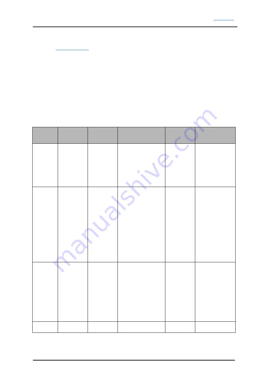
SmartDrive160 supports four different types of input mode. The DIP switch settings for each
mode and the function for input pin are summarized as below:
Input
Mode
DIP Switch
(SW1
SW4)
DIP Switch
(SW5
SW8)
Description
Input 1
Input 2
RC
0000XXXX
SW5:6
SW7
SW8
Single/Mix Mode
0X Single
10
Mix (Left)*
11
Mix (Right)*
Exponential Mode
MCU Mode
Speed
Steering (Mix
Mode)
Analog /
PWM
XX01XXXX
SW1:2
SW5:6
SW7
SW8
Analog/PWM Mode
00
Analog
11
PWM
Single/Mix Mode
0X Single
10
Mix (Left)*
11
Mix (Right)*
Exponential Mode
SignMagnitude Mode
(Single Mode only).
SW2 must be 0.
Speed
Steering (Mix
Mode)
Direction
(SignMagnitude)
Simplified
Serial
0010XXXX
SW5
SW6:8
N/A
UART Baud Rate
000 1200
001 2400
010 4800
011 9600
100 19200
101 38400
110 57600
111 115200
UART Rx
Slave Select
Packetized
Serial
0011XXXX
SW5:8
UART Slave Address
(0x00 – 0x0f)
UART Rx
N/A
0 – OFF
1 – ON
X – Don’t Care
* Left/Right is just for reference. Actual side of the motor may depends on the RC transmitter or analog/PWM
input.
Created by Cytron Technologies Sdn. Bhd. – All Rights Reserved
10


