Document # 001-20559 Rev. *D
55
4.
RAM Paging
This chapter explains the PSoC device’s use of RAM Paging and its associated registers. For a complete table of the RAM
Paging registers, refer to the
“Summary Table of the Core Registers” on page 32
. For a quick reference of all PSoC registers
in address order, refer to the
Register Details chapter on page 47
4.1
Architectural Description
The M8C is an 8-bit CPU with an 8-bit address bus. The 8-
bit memory address bus allows the M8C to access up to 256
bytes of SRAM, to increase the amount of available SRAM
and preserve the M8C
language.
The memory paging architecture consists of five areas:
■
Stack Operations
■
Interrupts
■
MVI Instructions
■
Current Page Pointer
■
Indexed Memory Page Pointer
The first three of these areas have no dependency on the
CPU_F register's PgMode bits and are covered in the next
subsections after Basic Paging. The function of the last two
depend on the CPU_F PgMode bits and are covered last.
4.1.1
Basic Paging
The M8C is an 8-bit CPU with an 8-bit memory address bus.
The memory address bus allows the M8C to access up to
256 bytes of SRAM. To increase the amount of SRAM, the
M8C accesses memory page bits. The memory page bits
are located in the CUR_PP register and allow for selection
of one of eight SRAM pages. In addition to setting the page
bits, Page mode must be enabled by setting the CPU_F[7]
bit. If Page mode is not enabled, the page bits are ignored
and all non-stack memory access is directed to Page 0.
Once Page mode is enabled and the page bits are set, all
instructions that operate on memory access the SRAM page
indicated by the page bits. The exceptions to this are the
instructions that operate on the stack and the MVI instruc-
tions: PUSH, POP, LCALL, RETI, RET, CALL, and MVI.
See the description of
below for a more detailed discussion.
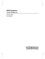
Figure 4-1. Data Memory Organization
Table 4-1. PSoC Device SRAM Availability
PSoC Device
Amount of SRAM
Number of Pages
CY8C24x23A
256 Bytes
1 Page
CY8C24533
256 Bytes
1 Page
CY8C23533
256 Bytes
1 Page
CY8C23433
256 Bytes
1 Page
CY8C24633
256 Bytes
1 Page
Page 0
SRAM
256 Bytes
ISR
Page 6
SRAM
256 Bytes
Page 5
SRAM
256 Bytes
Page 3
SRAM
256 Bytes
Page 2
SRAM
256 Bytes
Page 1
SRAM
256 Bytes
Page 7
SRAM
256 Bytes
Page 4
SRAM
256 Bytes
00h
FFh
Summary of Contents for PSoC CY8C23533
Page 4: ...Contents Overview 4 Document 001 20559 Rev D Section G Glossary 385 Index 401 ...
Page 16: ...Contents Overview 16 Document 001 20559 Rev D ...
Page 24: ...24 Document 001 20559 Rev D Section A Overview ...
Page 30: ...30 Document 001 20559 Rev D Pin Information ...
Page 54: ...54 Document 001 20559 Rev D Supervisory ROM SROM ...
Page 60: ...60 Document 001 20559 Rev D RAM Paging ...
Page 68: ...68 Document 001 20559 Rev D Interrupt Controller ...
Page 76: ...12 Document 001 20559 Rev D General Purpose IO GPIO ...
Page 82: ...18 Document 001 20559 Rev D Internal Main Oscillator IMO ...
Page 84: ...20 Document 001 20559 Rev D Internal Low Speed Oscillator ILO ...
Page 90: ...26 Document 001 20559 Rev D External Crystal Oscillator ECO ...
Page 94: ...30 Document 001 20559 Rev D Phase Locked Loop PLL ...
Page 106: ...42 Document 001 20559 Rev D Sleep and Watchdog ...
Page 228: ...164 Document 001 20559 Rev D Section D Digital System ...
Page 234: ...170 Document 001 20559 Rev D Array Digital Interconnect ADI ...
Page 278: ...214 Document 001 20559 Rev D Digital Blocks ...
Page 296: ...232 Document 001 20559 Rev D Analog Interface ...
Page 304: ...240 Document 001 20559 Rev D Analog Array ...
Page 308: ...244 Document 001 20559 Rev D Analog Input Configuration ...
Page 312: ...248 Document 001 20559 Rev D Analog Reference ...
Page 338: ...274 Document 001 20559 Rev D Section F System Resources ...
Page 354: ...290 Document 001 20559 Rev D Multiply Accumulate MAC ...
Page 374: ...310 Document 001 20559 Rev D I2C ...
Page 400: ...336 Document 001 20559 Rev D Section G Glossary ...