background image

2

4. Operation Controls and Functions

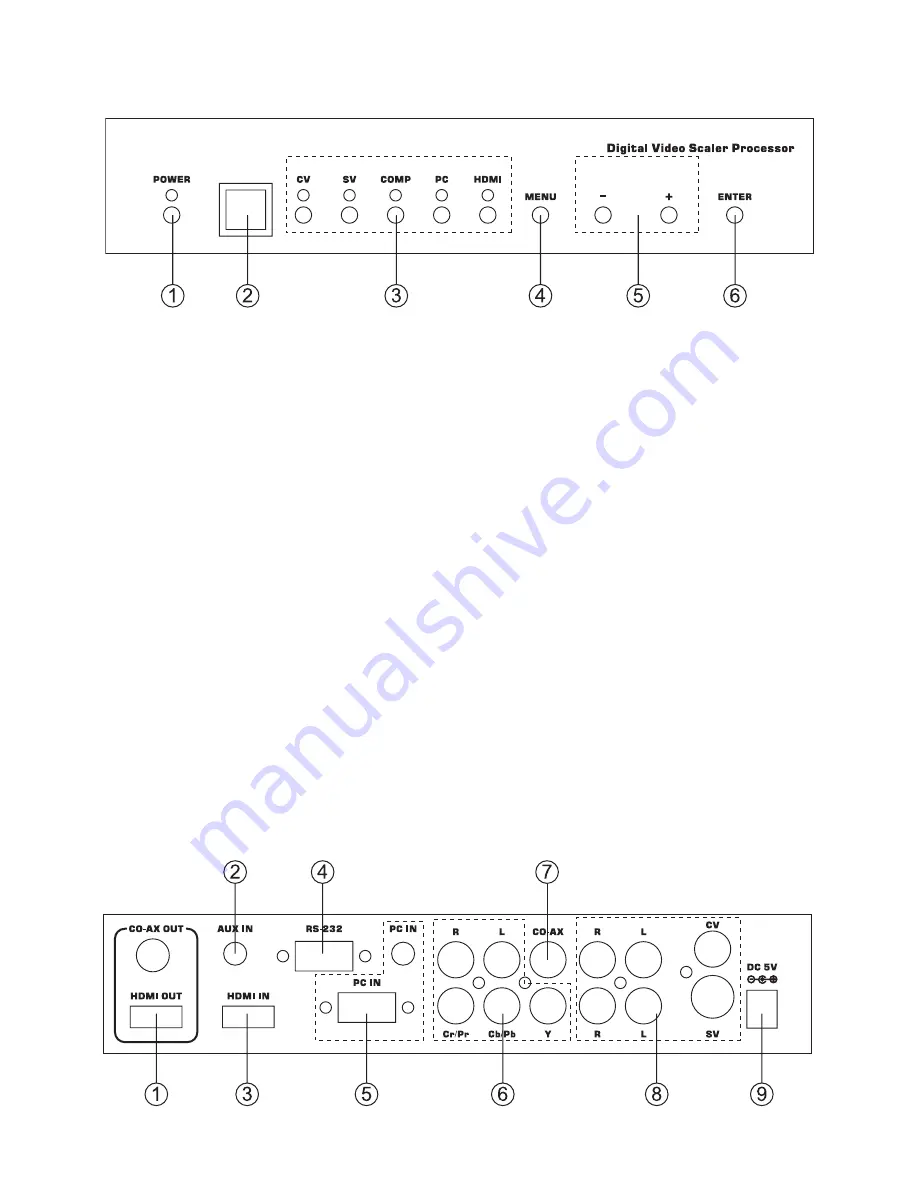
4.1. Front Panel

1. POWER Button and LED Indicator:

Press the button to turn ON/OFF the power of the unit. The LED will 

illuminate when the power is turned on.

2. IR remote control sensor.

3. Input Selection Buttons and LED Indicators:

Press each of the buttons (CV/SV/COMP/PC/HDMI) to select the 

desired input source. The LED will illuminate when the corresponding 

input is selected.

4. MENU Button: 

Press the MENU button to bring up OSD operation menu (see section 

“4.3 OSD Operation” for reference.)

5. +/- Buttons:

a. On the 

rst tier of OSD menu, use + and - buttons to move up/down 

the highlight item for selection. 

b. Once the desired option is selected, use + and - buttons to toggle 

between setting values.

6. ENTER Button:

In OSD menu, use the ENTER button to con

rm the selection.

4.2. Rear Panel

Summary of Contents for CM-390

Page 1: ...1 CV SV PC HD HDMI 1080p Scaler Box CP 255I Operation Manual ...

Page 2: ...2 ...

Page 3: ...4 Operation Controls and Functions 4 1 Front Panel 4 2 Rear Panel 4 3 OSD Operation 4 4 Remote Control 5 CP 255I RS 232 Remote Control Protocol 6 Specifications 6 1 General Specification 6 2 Support Resolution 7 Connection and Installation 1 1 1 2 2 2 4 5 6 9 9 9 10 ...

Page 4: ... WUXGA HD 480i 1080p resolutions to from another PC HD resolutions 3 Automatically detect the factory setting of the connected display and output the corresponding resolution and refresh rate when the NATIVE output is selected 4 Supports 50 60Hz frame rate conversion 5 Supports 3 D motion video adaptive 3 D de interlacing and 3 2 2 2 pull down detection and recovery 6 Provides output picture adjus...

Page 5: ...P PC HDMI to select the desired input source The LED will illuminate when the corresponding input is selected 4 MENU Button Press the MENU button to bring up OSD operation menu see section 4 3 OSD Operation for reference 5 Buttons a On the first tier of OSD menu use and buttons to move up down the highlight item for selection b Once the desired option is selected use and buttons to toggle between s...

Page 6: ...Pb Cb Pr Cr Video and L R Audio Input Connect the Y Pb Cb Pr Cr Component 3 RCA input ports to the Component output port of your video source equipment such as DVD player or Set Top Box And connect the L R audio input ports to the audio output port of your audio source equipment 7 CO AX Input The CO AX port provides the digital audio input support and can be used to combine with each video input s...

Page 7: ...n Color Level BLUE 0 100 of Blue Color Level EXIT Back to the 1st Tier OUTPUT NATIVE VGA SVGA XGA SXGA UXGA 480i 480p 720p 60Hz 1080i 30Hz 1080p 60Hz 576i 576p 720p 50Hz 1080i 25Hz 1080p 50Hz WXGA WSXGA WUXGA OSD HPOSITION 0 100 of OSD Horizontal Position VPOSITION 0 100 of OSD Vertical Position TIMER 0 100 of OSD Show Time sec TRANSP 0 100 of OSD Transparent Level EXIT Back to the 1st Tier AUDIO ...

Page 8: ...on For other output resolutions that are not covered by these buttons please enter OSD Menu to select them 7 MENU Press the button to bring up OSD main menu page 8 Exit Press the button to exit from a sub menu or main menu 9 Up Down Left Right Press the Up Down button to move the highlight bar to your desired parameter during the OSD operation Press the Left Right button to increase decrease the s...

Page 9: ...r with RS 232 modem cable Pins definition of modem cable RS 232 transmission format Baud Rate 19200 bps Data Bit 8 bits Parity None Stop Bit 1 bit CP 255I Remote Controller PIN Definition PIN Definition 1 NC 1 NC 2 TxD 2 RxD 3 RxD 3 TxD 4 NC 4 NC 5 GND 5 GND 6 NC 6 NC 7 NC 7 NC 8 NC 8 NC 9 NC 9 NC ...

Page 10: ...E 3 SIZE LETTERBOX SCALER LETTERBOX OUTPUT S SIZE 4 SIZE PANSCAN SCALER PANSCAN OUTPUT S PICTUREMODE 0 3 PICTUREMODE STANDARD USER 0 STANDARD 1 MOVIE 2 VIVID 3 USER PICTURE MODE OUTPUT S CONTRAST 0 100 CONTRAST 0 100 CONTRAST 0 100 ADJUST Defaut 50 S BRIGHTNESS 0 100 BRIGHTNESS 0 100 BRIGHTNESS 0 100 ADJUST Defaut 45 S HUE 0 100 HUE 0 100 HUE 0 100 ADJUST Defaut 50 S SATURATION 0 100 SATURATION 0 ...

Page 11: ...TUS R PCHPOSITION PCHPOSITION 0 100 SHOW PC H POSITION STATUS R PCVPOSITION PCVPOSITION 0 100 SHOW PC V POSITION STATUS R PCCLOCK PCCLOCK 0 100 SHOW PC COLOK STATUS R PCPHASE PCPHASE 0 63 SHOW PC PHASE STATUS R COLORTEMP COLORTEMP NORMAL USER SHOW COLOR TEMP STATUS R RED RED 0 100 SHOW COLOR TEMP RED STATUS R GREEN GREEN 0 100 SHOW COLOR TEMP GREEN STATUS R BLUE BLUE 0 100 SHOW COLOR TEMP BLUE STA...

Page 12: ...olution 480i 576i 480p 576p 720p 60 50 1080i 30 25 1080p 60 50 VGA 60 72 75 85 SVGA 56 60 72 75 85 XGA 60 70 75 85 SXGA 60 75 85 UXGA 60 WXGA 60 1280X800 WSXGA 60 1680X1050 WUXGA 60 1920X1200 Resolution INPUT Component D SUB DVI HDMI V V V V V V V V V V V V V V V V V V V V V V V V V V V V OUTPUT D SUB DVI HDMI 480i 576i 480p 576p 720p 60 50 1080i 30 25 1080p 60 50 VGA 60 72 75 85 SVGA 56 60 72 75 ...

Page 13: ...10 7 Connection and Installation TV HDMI Cable HDMI HDMI PC in Component S Video Composite ...

Page 14: ...11 ...

Page 15: ......

Page 16: ...i CM 393S Video S Video SCART HDMI HDMI 1080i CM 392 Video S Video HDMI 1080i CM 391 Video S Video DVI 1080i CM 390 Video S Video YPbPr HDTV RGB PC 1080i CSC 220 YPbPr YCbCr PC DVI D PC DVI D 1080i CS 720PHD SCART HDMI 720p fixed CV 720PHD Video S Video HDMI 720p fixed CP 254 DVI DVI 1080i CP 253 DVI YPbPr HDTV RGB PC 1080i CP 252 YPbPr HDTV RGB PC DVI 1080i CP 251F YPbPr HDTV RGB PC YPbPr HDTV RGB ...

Reviews: