


8
6. OPERATION CONTROLS AND FUNCTIONS
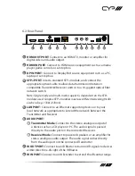
6.1 Front Panel
POWER T/R SOURCE
GbE VIDEO TX
LINK
RX
USB
MENU
-
+
ENTER
INFO
SDV-FTRX
1 2 3
5
4
6
7
8
1
POWER LED:
This LED will illuminate to indicate the unit is on and
receiving power.
2
T/R LED:
This LED indicates if the unit is in Transmitter (Green LED) or
Receiver (Amber LED) mode.
3
SOURCE LED:
This LED will illuminate to indicate that a local video
input is selected and live. Green indicates that the local HDMI input is
live and amber indicates that the local DisplayPort input is live.
Note: When the unit is in Receiver mode, and streaming is active, this LED
will remain off.
4
STREAMING STATUS LED BLOCK
A
GbE LED:
This LED will illuminate and blink to indicate a live and
active connection on the local gigabit Ethernet port.
B
VIDEO LED:
This LED will illuminate when a video signal is live on
the optical fiber streaming port. When no video is active the LED
will remain off, even if the streaming connection is valid.
C
TX & RX LINK LEDs:
These LEDs will illuminate and blink to
indicate data transmission and reception activity across the optical
fiber streaming connection.
5
MENU BUTTON:
Press to enter the OSD menu, or to back out from
menu items.
6
− (MINUS) BUTTON:
Press to move down or adjust selections within
OSD menus. When not in a menu, press to manually switch between
the available inputs.
7
+ (PLUS) BUTTON:
Press to move up or adjust selections within OSD
menus. When not in a menu, press to manually switch between the
available inputs.
8
ENTER/INFO BUTTON:
When inside an OSD menu, press to confirm a
selection within the OSD or to go deeper into a menu item. When not
in a menu, press to activate the Information OSD.