


3
6. OPERATION CONTROLS AND FUNCTIONS
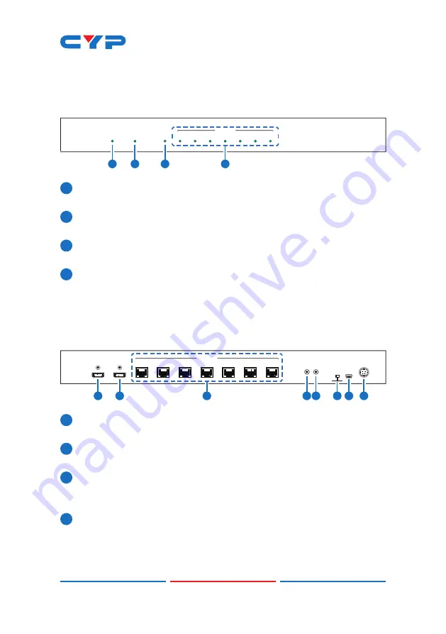
6.1 Front Panel
POWER
SYNC
HDMI
LINK
LINK 1
LINK 2
LINK 3
LINK 4
LINK 5
LINK 6
LINK 7
CAT5e/ 6 / 7 OUT
1
2
3
4
1
POWER LED
: The LED will illuminate when connected to an active
power supply.
2
SYNC LED:
This LED will illuminate when the HDMI input is connected
to a HDMI source and receiving a signal.
3
HDMI OUT LINK LED:
This LED will illuminate when HDMI output is
connected to TV or display monitor and receiving a signal.
4
CAT5e/6/7 OUT LINK 1~7 LEDs:
The link LEDs will illuminate when the
receivers are connected to the CAT 5e/6/7 outputs are connected
to TVs or displays and displaying a signal.
6.2 Rear Panel
1
HDMI OUT
HDMI IN
2
3
4
5
6
7
SERVICE
CAT5e/ 6 / 7 OUT
STD TV
DC 24V
IR IN IR OUT
EDID
4
2
1
3
5
6 7
8
1
HDMI IN:
Connect to HDMI equipped source equipment such as a
DVD/Blu-ray player or games console.
2
HDMI OUT:
Connect to a HDMI display for local monitoring of the
HDMI signal or cascade to another Splitter.
3
CAT5e/6/7 OUT 1~7:
Connect to CAT5e/6/7 to HDMI Receivers (with
or without PoE) with a single CAT5e/6/7 cable each to extend the
HDMI signal up to 60 m.
4
IR IN:
Connect the supplied IR Receiver cable for IR signal
reception. Ensure that remote being used is within the direct line-
of-sight of the IR Extender
.


