background image

16

wall dimensions. Options are: 1×1, 1×2, 1×3, 1×4, 2×2, 3×3

2)  Bezel Settings:

 Configures the bezel size to compensate for around 

all displays.


Note: Bezel settings assume that the top/bottom and left/right bezel 

pairs are uniform in size and all displays in the video wall share the same 

dimensions.

  Bezel Enable:

 Click this button to enable or disable the use of 

bezel compensation.

 Horizontal:

 Set the size, in pixels, of the vertical bezel 

compensation. (Maximum value is 50)

 Vertical:

 Set the size, in pixels, of the vertical bezel compensation. 

(Maximum value is 50)

3)  Set Button:

 After fully defining all components of the video wall, or 

after making changes to an existing layout, click this button to confirm 

the new settings and transmit them to the connected units.

6.4.4 Settings Tab

The basic configuration and settings for each connected unit can be set 

here by selecting the unit to configure from the “ID-NAME” list on the left 

side. To exit the setting configuration tabs and return to the layout mode, 

click on the “Layout” button in the upper-right section of the window.

Summary of Contents for DS-MSC14-4K22

Page 1: ...DS MSC14 4K22 1 to 4 Multi screen Controller with 4K HDR Input Support and HDCP2 2 OPERATION MANUAL ...

Page 2: ......
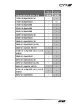
Page 3: ...d reserves the right to make improvements to this document and or product at any time and without notice COPYRIGHT NOTICE No part of this document may be reproduced transmitted transcribed stored in a retrieval system or any of its part translated into any language or computer file in any form or by any means electronic mechanical magnetic optical chemical manual or otherwise without express writt...

Page 4: ...ver push an object of any kind into this product through any openings or empty slots in the unit as you may damage parts inside the unit Do not attach the power supply cabling to building surfaces Use only the supplied power supply unit PSU Do not use the PSU if it is damaged Do not allow anything to rest on the power cabling or allow any weight to be placed upon it or any person walk on it To pro...

Page 5: ...unctions 8 6 1 Front Panel 8 6 2 Rear Panel 9 6 3 RS 232 Pinout and Defaults 10 6 4 Video Wall App 11 6 5 Telnet Control 21 6 6 Serial and Telnet Commands 22 7 Connection Diagram 28 8 Specifications 29 8 1 Technical Specifications 29 8 2 Video Specifications 30 8 3 Audio Specifications 32 8 4 Cable Specifications 33 9 Acronyms 34 ...

Page 6: ...ns including Internal External and User configurations as well as advanced HDCP management allows this video wall processor to handle almost any source situation Additionally multiple video wall processors can be used together to generate video walls with configurations as large as 8 8 A dedicated PC application allows the user to fully customize the video wall and associated features Additional c...

Page 7: ...4 8 bit HDMI output resolution is fixed at 1080p 60Hz Supports 10 bit and 12 bit HDR High Dynamic Range input with automatic conversion to standard range 8 bit prior to output Supports pass through of many audio formats including LPCM up to 8 channels Bitstream and HD Bitstream A single unit supports 2 2 video wall generation multiple units can be user together to generate video walls up to 8 8 Su...

Page 8: ...EDs will illuminate to indicate when a valid sink has been detected on the associated output port When no sink is detected the LED will remain off 2 IN LED This LED will illuminate green to indicate that a live source has been detected on the input port When no source is detected the LED will illuminate amber ...

Page 9: ...evice to send RS 232 commands to control the unit directly or via PC App 3 SERVICE Port This port is reserved for firmware update use only 4 CONTROL Port Connect directly or through a network switch to your PC laptop to control the unit via Telnet PC App 5 HDMI IN Port Connect to HDMI source equipment such as a media player game console or set top box 6 HDMI OUT A D Ports Connect to HDMI TVs monit...

Page 10: ...6 3 RS 232 Pinout and Defaults Serial Port Default Settings Baud Rate 19200 Data Bits 8 Parity Bits None Stop Bits 1 Flow Control None 1 2 3 4 5 8 7 6 9 DCD RxD TxD DTR GND RI CTS RTS DSR DE 9 Female Port ...

Page 11: ...settings if needed 6 4 1 Software Operation Please obtain the Video Wall App software from your authorized dealer and save it in a directory where you can easily find it Ensure that all the units you wish to control have been powered on and that they are all connected to the same network as your laptop PC Start the software by double clicking on the exe file to start the Video Wall App software By...

Page 12: ...e Layout tab Note Units connected via RS 232 can t be directly detected so all available serial ports will be listed even if they do not currently have a connected unit 1 All Units List All detected units on the local network as well as all available local serial ports are listed here All detected units are identified by their IP address Selecting a Unit or serial port and then clicking the right ...

Page 13: ...remove an individual unit from the list click the x in the unit s Del column Arrange Button To re order the units in the list type new ID numbers next to each unit and click on this button Note ID numbers can only be changed while a unit is disconnected Clear Button Click this button to remove all units from the Selected Units list ...

Page 14: ...the software from all units The Stat column will show a gray circle next to disconnected units 6 4 3 Layout Tab The Layout Tab provides control over the dimensions of the video wall as well as how much bezel compensation to apply The video wall s general appearance and the position of the 4 displays connected to each unit is represented by the large window to the right Each display is labeled with...

Page 15: ...ximum of 64 displays can be supported 8 8 video wall Column Sets the number of displays in the video wall measured horizontally Maximum is 8 displays Row Sets the number of displays in the video wall measured vertically Maximum is 8 displays Quick Selection Provides a quick way to select common video ...

Page 16: ...l compensation Maximum value is 50 Vertical Set the size in pixels of the vertical bezel compensation Maximum value is 50 3 Set Button After fully defining all components of the video wall or after making changes to an existing layout click this button to confirm the new settings and transmit them to the connected units 6 4 4 Settings Tab The basic configuration and settings for each connected uni...

Page 17: ...way to update the unit s firmware Insert a USB thumb drive with a valid firmware file bin format in the root directory into the unit s USB service port then click the Update FW button After the update is complete the unit will automatically reboot Factory Reset Selecting this will reset the unit s settings back to their factory defaults 2 Network Menu This window displays the unit s MAC address an...

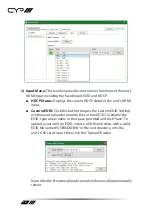
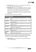
Page 18: ...is button to open the Custom EDID Settings window and upload or rename the custom EDID To rename the EDID type a new name in the space provided and click Save To upload a custom User EDID insert a USB thumb drive with a valid EDID file named USEREDID BIN in the root directory into the unit s USB service port then click the Upload button Note After the firmware upload is complete the unit will auto...

Page 19: ...lt EDIDs FHD 2CH 1920 1080p 60Hz 4 95Gbps 8 bit color LPCM 2 0 FHD MCH 1920 1080p 60Hz 4 95Gbps 8 bit color LPCM 7 1 Bitstream UHD 2CH 3840 2160p 30Hz 10 2Gbps Deep Color 8 10 12 bit LPCM 2 0 UHD MCH 3840 2160p 30Hz 10 2Gbps Deep Color 8 10 12 bit LPCM 7 1 Bitstream 4K UHD 2CH 3840 2160p 60Hz 18Gbps Deep Color 8 10 12 bit LPCM 2 0 4K UHD MCH 3840 2160p 60Hz 18Gbps Deep Color 8 10 12 bit LPCM 7 1 B...

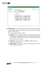
Page 20: ...utputs OSD Info Select the behavior of the informational OSD Selecting Off disables it completely selecting On will always display the OSD and selecting Info will only show the OSD for a few seconds after a source or sync change Audio Out Click the speaker icon to enable or disable muting the audio output Output Status Displays the current connection and HDCP status of all 4 of the unit s outputs ...

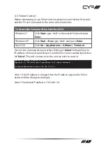
Page 21: ...pplications Utilities Terminal Once in the Command Line Interface CLI type telnet followed by the IP address of the unit and the port number if it is non standard and then hit Enter This will connect us to the unit we wish to control Microsoft Windows Version 6 1 7601 Copyright c 2009 Microsoft Corporation All rights reserved C Users Adminstrator telnet 192 168 1 50 23 Note 1 If the IP address is ...

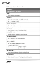
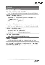
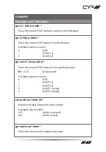
Page 22: ...del name get fw ver Show the unit s current firmware version set update mcu Initiate firmware update via the USB port set factory default Reset the unit to the factory defaults set ip mode N1 Set the IP address assignment mode Available values for N1 0 Static IP mode 1 DHCP mode get ip mode Show the current IP address assignment mode get ipconfig Show the unit s current IP configuration informatio...

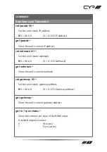
Page 23: ...etmask N1 Set the unit s static netmask N1 X X X X X 0 255 Netmask get netmask Show the unit s current netmask set gateway N1 Set the unit s static gateway address N1 X X X X X 0 255 Gateway address get gateway Show the unit s current gateway address get in 1 sync status Show the current sync state of the HDMI input Available response values 0 No sync 1 Sync active ...

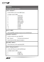
Page 24: ...nk A 9 Sink B 10 Sink C 11 Sink D get in 1 edid Show the EDID currently being used on the HDMI input set edid 7 name N1 Set the name for the specified EDID N1 Name 32 characters maximum Note Only User EDIDs may be renamed get edid 7 name Show the name for the specified EDID set in 1 hdcp mode N1 Set the HDCP behavior of the HDMI input Available values for N1 0 Disable 1 Follow in 2 Follow out ...

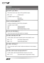
Page 25: ...e values 0 Off 1 HDCP1 x 2 HDCP2 2 get out N1 hdcp status Show the current HDCP status of the specified output N1 A D Output port Available response values 0 Off 1 HDCP1 x 2 HDCP2 2 3 HDCP1 x failed 4 HDCP2 2 failed set audio out mute N1 Enable or disable muting the audio output Available values for N1 OFF Audio unmuted ON Audio muted get audio out mute Show the current audio output mute state ...

Page 26: ...OSD always on INF Momentary display mode get out osd info display Show the current info OSD state for all outputs set video wall layout N1 N2 Set the video wall s total horizontal and vertical display count N1 1 8 Horizontal display total N2 1 8 Vertical display total get video wall layout Show the video wall s current total horizontal and vertical display count set video wall h bezel compensation...

Page 27: ... ON Enabled get video wall bezel mode Show the current state of the video wall s bezel compensation mode set video wall unit index N1 Set the unit s video wall index number N1 0 15 Video wall index number get video wall unit index Show the unit s current video wall index number set user 1 edid data Initiate uploading a new User EDID to the unit via the USB port Note Commands will not be executed u...

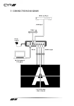
Page 28: ...28 7 CONNECTION DIAGRAM DC 24V RS 232 CONTROL IN D C B A SERVICE OUT 4K Blu ray Player HDMI Input HDMI Outputs 2 2 TVs Displays Total 4 Screens Router Power Supply RS 232 Equipped PC Laptop RS 232 ...

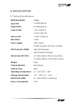
Page 29: ...200 Power Supply 24V 1 25A DC US EU standards CE FCC UL certified ESD Protection HBM 8kV Air Discharge 4kV Contact Discharge Dimensions W H D 231 5mm 44mm 167mm Case Only 231 5mm 44mm 174mm All Inclusive Weight 652g Chassis Material Metal Steel Chassis Color Black Operating Temperature 0 C 40 C 32 F 104 F Storage Temperature 20 C 60 C 4 F 140 F Relative Humidity 20 90 RH Non condensing Power Consu...

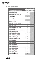
Page 30: ...80i 60 720 480p 60 720 576i 50 720 576p 50 800 600p 56 60 72 75 85 848 480p 60 1024 768p 60 70 75 85 1152 864p 75 1280 720p 50 60 1280 768p 60 75 85 1280 800p 60 75 85 1280 960p 60 85 1280 1024p 60 75 85 1360 768p 60 1366 768p 60 1400 1050p 60 1440 900p 60 75 1600 900p 60RB 1600 1200p 60 1680 1050p 60 1920 1080i 50 60 ...

Page 31: ...1200p 60RB 2560 1440p 60RB 2560 1600p 60RB 2048 1080p 24 25 30 2048 1080p 50 60 3840 2160p 24 25 30 3840 2160p 50 60 4 2 0 3840 2160p 24 HDR10 3840 2160p 50 60 4 2 0 HDR10 3840 2160p 50 60 4096 2160p 24 25 30 4096 2160p 50 60 4 2 0 4096 2160p 24 HDR10 4096 2160p 50 60 4 2 0 HDR10 4096 2160p 50 60 ...

Page 32: ... bit 4 4 4 8 bit 4 4 4 8 bit High Speed HDMI Cable HDMI Input 15m 10m 5m 3m HDMI Output 15m 10m Bandwidth Category Examples 1080p FHD Video Up to 1080p 60Hz 12 bit color Data rates lower than 5 3Gbps or below 225MHz TMDS clock 4K30 UHD Video 4K 24 25 30Hz 4K 50 60Hz 4 2 0 8 bit color Data rates higher than 5 3Gbps or above 225MHz TMDS clock but below 10 2Gbps 4K60 UHD Video 4K 50 60Hz 4 4 4 8 bit ...

Page 33: ...t Protection HDMI High Definition Multimedia Interface HDR High Dynamic Range IP Internet Protocol kHz Kilohertz LAN Local Area Network LED Light Emitting Diode LPCM Linear Pulse Code Modulation MAC Media Access Control MHz Megahertz OSD On Screen Display TCP Transmission Control Protocol TMDS Transition Minimized Differential Signaling UHD Ultra High Definition 10 2Gbps UHD Ultra High Definition ...

Page 34: ...CYP UK Ltd Unit 7 Shepperton Business Park Govett Avenue Shepperton Middlesex TW17 8BA Tel 44 0 20 3137 9180 Fax 44 0 20 3137 6279 Email sales cypeurope com www cypeurope com v1 01 ...

Reviews: