5
8
IR OUT 1~4:
Connect the IR blasters for IR signal transmission. Place
the IR blaster in direct line-of-sight of the equipment to be
controlled.
9
ALL IR OUT:
Connect to the IR blaster for IR signal transmission of the
source or display equipment. Place the IR blaster in direct line-of-
sight of the equipment to be controlled.
10
ALL IR IN:
Connect to the IR extender for IR signal reception of the
remote control of this device or the source and display equipment.
Ensure that remote being used is within the direct line-of-sight of
the IR extender.
11
DC24V:
Connect the 24 V DC power supply to the unit and plug the
adaptor into an AC outlet.
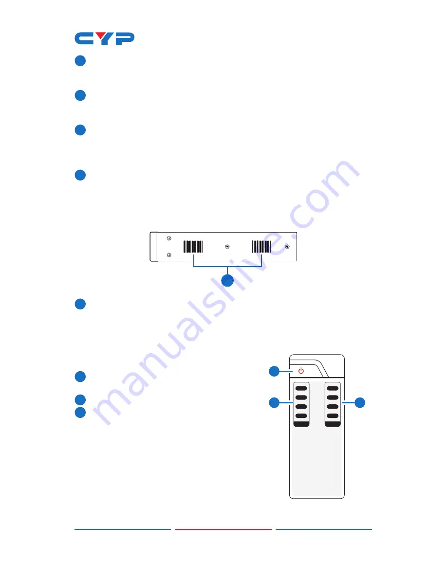
6.3 Side Panel
1
1
Fan Ventilator:
These are fan ventilation areas, DO NOT block these
areas or cover them with any object. Ensure there is adequate
space around the unit for air to circulate.
6.4 Remote Control
1
POWER:
Press this button to switch on the
device or set it to standby mode.
2
1~4 IN:
Input ports selection 1~4.
3
A~D OUT:
Output ports selection A~D.
Note: IR Matrix control from Zones only
require the user to select the desired
input.
1
A
B
2
C
3
4
D
CR-121
IN
OUT
1
2
3
Summary of Contents for CMSI-424E
Page 2: ......
Page 19: ......
Page 20: ...Home page http www cypress com tw CYPRESS TECHNOLOGY CO LTD ...


