


2
Operation Control and Functions
Top Panel
+
-
MENU
INPUT
POWER
Power button:
The unit enters into standby status when 12 V DC power is fed into
the power jack on the back panel . Press the power button to turn
on the unit ( LED illuminates in green color ); press again to return
to standby mode ( LED illuminates in red).
1
1
Power ON / Standby indicator:
When power button is pressed, the unit is turned on, and the LED
illuminates in green color. The unit is then ready for operation.
When the unit is under standby mode, all control buttons will not
function, Only the PC input is looping through to the VGA output.
2
3
4
5
Front
Panel
2
Power ON /
Standby LED
When in OSD mode. Press the button to move up or down the hightlight
bar to your desired parameter. Or after a parameter been selected by
MENU/Enter button, press the button to alter the value of your selected
parameter.
5
Input Selection :
Press the button to select between SCART input and PC-loop throught.
When scart input is selected CM-345S will outomatically detect the
SCART input as a RGB signal or composite video signal.
3
MENU / ENTER :
Press the button to enter into OSD menu or to confirm your selection
of the highlighted parameter.
4
+ / - :
Installation
6
On the sound Sub-menu, you can select to "mute" audio out.
In Resolution Sub-menu, you can select output resolution from:
640 X 480, 800 X600, or 1024 X 768.
3
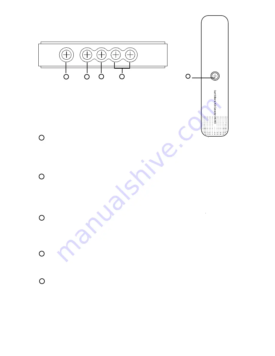
1. Power socket: 12V 800mA DC input.
2. Scart RGB or composite video input connector.
3. Audio out: Stereo audio L/R output.
4. PC audio in: 3.5mm PC audio input.
5. PC in: 15-pin D-Sub PC VGA input.
6. PC out: 15-pin D-Sub PC VGA output.
1. Audio O/P 1, Right Channel
2. Audio I/P 1, Right Channel
3. Audio O/P 2, Left Channel
4. GND (Audio)
5. GND (Blue)
6. Audio I/P 2, Left Channel
7. RGB I/P, Blue(B)
8. Switch Signal Video (No use)
9. GND (Green)
10. Not Connected
11. RGB I/P, Green (G)
12. Not Connected
13. GND (Red)
14. Not Connected
15. RGB I/P, Red (B)
16. Switch Signal RGB (Blanking)
17. GND (Video)
18. GND (Blanking)
19. Video O/P
20. Video I/P
21. Shield
Rear Panel
Scart pin configuration
PC OUT
PC IN
PC
AUDIO
IN
AUDIO OUT
L
R
SCART IN
POWER
DC 12V
1
2
3
4
5
6
*
*
1
3
5
7
9
11
13
15
17
19
21
2
4
6
8
10
12
14
16
18
20
4
Use +, - to move up or down the high-light bar to your desired parameter.
Press MENU/ENTER to confirm your selection.
To adjust the setting value of your selected parameter, press " + " to increase
the value. Press " - " to decrease the value.
Use buttons on the remote or button on top panel
to move hightlighted bar to your desired parameter.
press MENU / ENTER to enter into sub-menu, and use + - ,
to move to your desired selection. When a parameter is
selected, its color will be inverted.
.
On the source Sub-menu, you can choose input between scart, and PC
pass through.
On the picture Sub-menu, you can adjust setting value of the follwing parameters.
Use channel up or down to select your desired adjustment parameter.
Brightness: Use /- to increase or decrease brightness level.
Contrast: Use /- to increase or decrease contrast level.
Color: Use /- to increase or decrease color saturation level.
Tint(NTSC only): Use /- to increase or decrease Tint level.
Sharpness: Use /- to increase or decrease the sharpness level.
Reset: To recall the preset default value.
Exit: Return to previous Menu page.
Installation
5
Installation
Power up the unit:
1. Plug the power jack into the power socket on the back of the unit,
the power LED will illuminate in red color(Standby mode).
2. Press the power button, power LED will turn into green light.(operation mode)
3. Press the power button again will return to standby mode.
4. When the unit first powered up the default input to the unit is Scart
When you changed input source and later power down the unit the last input
source you selected will be memorized by the unit. When you re-power the
unit the memorized input will be recalled as input source.
OSD operation:
After power on the unit. Press the Menu button will bring up the main menu
page to your screen as bellow:


