

4
6. OPERATION CONTROLS AND FUNCTIONS
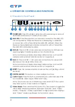
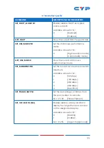
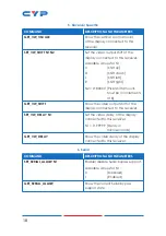
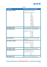
6.1 Receiver's Front Panel
POWER
USB 2.0
LINK
USB
RESET
CH+
CH-
MODE
SWITCH
ISP
SEL
IR
OUT
IR
RS-232
USB 1.1
LINK
IR
IN
1 2
3
4
6
5
7 8 9 10 11 12
13
1
POWER LED:
This LED will flash while the unit is powering on and will
illuminate solidly once it is ready to be used.
2
LINK LED:
If the Receiver has no network connection the LINK LED
will not illuminate. While the Receiver is attempting to establish
a connection with a Transmitter the LINK LED will flash. When the
Receiver has established a stable connection with a Transmitter
the LINK LED will illuminate solidly.
3
USB 2.0:
These 2 USB 2.0 slots provide connections for USB devices
requiring higher transfer speeds such as thumb drives.
Note: Isochronous (steady streaming) data devices such as USB
cameras and external hard drives are not supported.
4
USB 1.1:
These 2 USB 1.1 slots provide connections for slower USB
devices such as keyboards, mice, etc.
Note: Isochronous (steady streaming) data devices such as USB
cameras and external hard drives are not supported.
5
RESET:
Press this recessed button to reboot the unit (Settings will not
be reset).
6
SWITCH/MODE:
This button controls multiple functions:
a
Switch Input:
Press this button momentarily to switch between the
two available video inputs (HDMI and VGA).
Note: Due to the nature of streaming video and HDCP, the switch
may take up to 6–10 seconds to complete.
b
Video Mode:
Press and hold this button for 3 seconds to toggle the
video data streaming method between “Graphic” and “Video”
modes. “Graphic” mode is optimized for high-detail static displays
and “Video” mode is optimized for full motion video.


