7
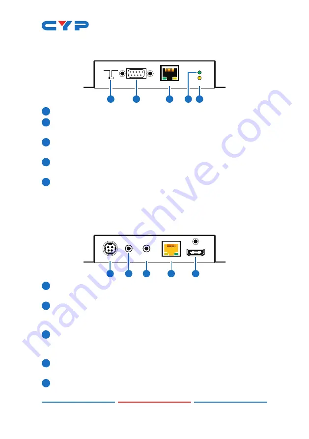
6.3 Receiver's Front Panel
POWER
LINK
RS-232 OUT
STD UPDATE
LAN
1
2
5
4
3
1
STD/UPDATE:
This switch is reserved for factory use only.
2
RS-232 OUT:
Connect to a PC, laptop or other serial control device
to send control commands to a compatible Transmitter.
3
LAN:
Connect to an Ethernet device or to your local network as
appropriate.
4
POWER LED:
This LED will illuminate to indicate the unit is on and
receiving power.
5
LINK LED:
This LED will illuminate solid when both Transmitter and
Receiver are connected and communicating with each other
properly.
6.4 Receiver's Rear Panel
CAT5e/6/7 IN
IR2
EXTENDER
IR1
BLASTER
HDMI OUT
DC 48V
2
1
3
4
5
1
DC 48V:
Plug the 48V DC power adapter into this port and connect
it to an AC wall outlet for power.
2
IR1 BLASTER:
Connect to the supplied IR Blaster cable for IR signal
transmission. Place the IR Blaster in direct line-of-sight of the
equipment to be controlled. (Requires compatible Transmitter.)
3
IR2 EXTENDER:
Connect to the supplied IR Extender cable for IR
signal reception. Ensure that remote being used is within the direct
line-of-sight of the IR Extender. (Requires compatible Transmitter.)
4
CAT5e/6/7 IN:
Connect to a compatible HDBaseT Transmitter with
a single Cat.5e/6/7 cable for transmission of all data signals.
5
HDMI OUT:
Connect to an HDMI TV, monitor or amplifier for digital
video and audio output.
Summary of Contents for CH-2527RX
Page 2: ......
Page 24: ...CYPRESS TECHNOLOGY CO LTD www cypress com tw ...


