background image

13

126221.PDF

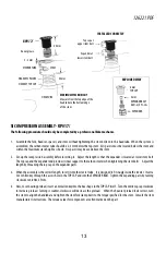
STEERER TUBE

KP017/

HEADTUBE

STEM

2 - 3 mm

HEADSET TOP CAP

HEADSET SPACERS

48 mm

Do not grease.

M

A

XIMUM ST

A

CK HEI

G

HT

Measure from the top edge of the 
headtube to the bottom edge 
of the stem.


55mm

5 mm
EXPANDER BOLT

 +#)+(

6 mm

TOP CAP

EXPANDER

EXPLODED VIE

W

Top cap at 

upper stem bolt 

Expander at 

lower stem bolt 

I

N

ST

A

LLED CO

RR

ECTLY

SI COMP

R

ESSIO

N


A

SSEMBLY - KP017/

The following procedure should only be completed by a professional bike mechanic. 

1.  Assemble the fork, headset, spacers, and stem without tightening the stem bolts onto the headtube.  When the system is 

assembled, the carbon steerer tube should be 2-3 mm below the top stem.  All spacers must be located below the stem and 
within the maximum stack height as shown. No spacers may be used above the stem.

2.  Set-up the compression assembly before inserting it.   Adjust the length so that the expander is located at lower stem bolt.  

The top cap and the expander end provides critical support to the carbon steerer when tightening the stem bolts.     Adjust the 
length by  threading the top cap on the expander parts.  

3.  When the assembly is the correct length,  insert it into the steerer tube.   It is designed to fit snugly inside the steerer.  Insert a 

5 mm Allen key through the access hole in the TOP CAP and into the EXPANDER BOLT.  Tighten the expanding parts by turning 
clockwise to 6.8Nm, 5 ftLbs.

4.  Now, to set bearing preload, insert a 6mm allen key into the hex shape  in the TOP CAP itself.    Turn the entire top cap clockwise 

to increase preload.  Turning it counter-clockwise will decrease the preload.    When the headset preload feels correct, turn 
the stem to align the handlebar and tighten the stem fork clamp bolts to the torque specified for the stem.  Consult the stem 
manufacturer’s instructions.  The torque values for components are often marked on the part. 

Summary of Contents for cannondale QUICK FULL CARBON 2012

Page 1: ...R S MANUAL SUPPLEMENT WARNING READ THIS SUPPLEMENT AND YOUR CANNONDALE BICYCLE OWNER S MANUAL Both contain important safety information Keep both for future reference 2012 QUICK FULL CARBON 126221 PDF 04 10 ...

Page 2: ... 1995 norme NFR030 In this supplement particularly important information is presented in the following ways WARNING Indicates a hazardous situation which if not avoided could result in death or serious injury NOTICE Indicates special precautions that must be taken to avoid damage TIP A TIP provides helpful information ...

Page 3: ... seat post Since your carbon seat post can also be damaged by clamping force adjust the stand clamp for the minimum clamping force needed to secure the bike Also before clamping clean the post and protect the seat post finish with a rag INSPECTION CRASH DAMAGE OF CARBON FRAMES FORKS WARNING AFTER A CRASH OR IMPACT Inspect frame carefully for damage See PART II Section D Inspect For Safety in your ...

Page 4: ...d NOTICE OBSERVETHE INSERT LIMIT NEVER USE SOLVENTS OR SPRAY CLEANERS DON T USE GREASE ALWAYS USE CARBON GEL Cannondale in kitKF115 is a small quantity enough for two or three applications DO NOT INSTALL THE SEAT POST SOTHAT IS BOTTOMED OUT INSIDETHE SEATTUBE Riding with the seat post bottomed out in the frame may damage the frame NEVER FORCETHE SEAT POST INTOTHE FRAME ALWAYS USE ATORQUEWRENCH WAR...

Page 5: ...3 126221 PDF MINIMUM INSERT 80 mm INSERT LIMIT 140 mm SEAT BINDER SEAT POST SEATTUBE Saddle not shown SEAT BINDER BOLTS 5 Nm 44 In Lbs MAXIMUM TORQUE Tighten bolts uniformly APPLY CARBON GEL KF115 ...

Page 6: ...ENANCE Periodically remove the seat binder from the frame clean the binder and inside the seat tube Toremovethebinderassembly completelyremovebothseatbinderboltsoutthroughthesmall frame holes Then remove the small retaining screw at the front of the binder Lift the binder and the wedge up out of the top of the seat tube ...

Page 7: ...mp grooves SADDLE RAILS CORRECT 7mm WARNING Incorrect alignment of the saddle clamp parts can result in the saddle moving unexpectedly while riding When adjusting the saddle angle make sure the saddle rails on both sides of the saddle are aligned with the inner and outer clamp on both sides of the saddle Ask your Cannondale Dealer for assistance YOU CAN BE SEVERELY INJURED PARALYZED OR KILLED IFYO...

Page 8: ... guide make sure the ferrule which must be used locates into the guide seat before the cable is tensioned Thereartoptubebrakeguideisremovable Theguideissecuredinthe tube opening by brake cable tension Make sure the guide is seated properly in the top tube opening when installing and connecting the rear brake Thefrontandrearderailleursatthebottombracketopeningandpass through the BB cable guide SERI...

Page 9: ...fully Check derailleur adjustment after replacement Readjust wheel quick release so it is very tight See PART I Section 4 A in your Cannondale Bicycle Owner s Manual The smaller M4 size outer bolt threaded into the inner may be used as connecting point for compatible fenders racks Be sure to use the specified Loctite and a torque wrench when tighening this fastener NOTICE Do not use a derailleur h...

Page 10: ...ld be smooth quietly No bearing play or movement inside the shell If the bearing is damaged replace both bearings with new ones BOTTOM BRACKET The bottom bracket shell is compatible with the BB30 Standard See http www bb30standard com The SI bottom bracket adapter enables the use of standard English 68mm bottom bracket cranksets KB6180 Standard KP018 Ceramic CIRCLIPS QC616 BOTTOM BRACKET SHELL Cir...

Page 11: ...h quality bicycle bearing grease to both sides of each bearing to help repel moisture BEARING REMOVAL 1 Toremovethebearings position CannondaletoolKT011 behind the bearing so that the tool ridges are seated on the bearing 2 Insert a driver punch or drift from the opposite side Locate it on the back of the tool and use light tapping to drive the bearing from the shell NOTICE Frequent or routine ren...

Page 12: ...ened with alcohol 5 The groove side of the adapter must be located on the drive side With a headset press the ADAPTER until the groove side face is flush with the drive side face of the SI BB shell Allow at least 12 hours at 72 F for the Loctite to cure before installing the standard bottom bracket crankset FollowLoctiteTechnicalDataSheethttp tds loctite com tds5 docs 609 EN PDF NOTICE We strongly...

Page 13: ...et shell Following removal it will be necessary to clean all remaining Loctite residue with a before reinstalling the SI circlips and bearings Use Loctite 768 Use a dental pick to remove any adhesive from the grooves Do not cut face or use abrasives to clean the inside if the BB shell For Loctite clean up instructions http tds loctite com 68mm ADAPTER RECEIVER DRIVE SIDE DRIVER KF366 ADAPTER EXTRA...

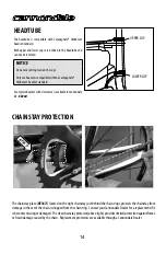
Page 14: ...ofessional bike mechanic first The fork must not be modified in any way to mount accessories Headset WARNING ONLYUSE CANNONDALECOMPRESSIONASSEMBLY KP017 Do not use a star nut or any other compression or expanding wedge assembly DO NOT INSTALL HEADSET SPACERS ON TOP OF THE STEM Installing spacers above the stem will raise the TOP CAP inside the steerer removing necessary support for the steerer tub...

Page 15: ...sion assembly before inserting it Adjust the length so that the expander is located at lower stem bolt Thetopcapandtheexpanderendprovidescriticalsupporttothecarbonsteererwhentighteningthestembolts Adjustthe length by threading the top cap on the expander parts 3 When the assembly is the correct length insert it into the steerer tube It is designed to fit snugly inside the steerer Insert a 5 mm All...

Page 16: ...or aboveright provideslimitedprotectionagainstframe or finish damage caused by the chain Replacement protectors are available through a Cannondale Dealer HEADTUBE The headtube is compatible with Campagnolo Hiddenset headset standard Both upper and lower cups are bonded in the headtube and can not be removed NOTICE Do not use cutting tools on the cups Only use headsets compatible with the Campagnol...

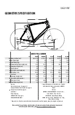
Page 17: ...4 61 9 62 8 65 4 M HeadTube Length cm 14 13 16 19 22 Headset Campy style bearings 41 8mm OD w 45 chamfers Headset Compression See page 12 Cannondale SI Compression Assembly KP017 Seatpost Minimum Insert Depth See page 2 80 mm Z Seatpost Insert Limit See page 2 140 mm Seat Binder KP153 MAXIMUMTORQUE 5 Nm 44 In Lbs Dropout Spacing Front 100 mm Rear 130 mm INTENDED USE See page 1 CONDITION 2 General ...

Page 18: ...L ROAD 34 50 170 KA015 172BLK KIT CRANKSET SL ROAD 34 50 172 KA015 175BLK KIT CRANKSET SL ROAD 34 50 175 Spindle Kits QC690 KIT BB CDALE Si 68X104mm Rd QC850 KIT BB CDALE Si 68X104mm Rd SRM KA019 KIT BB CDALE Si 68X104 CERAMIC Crankarms KP020 170L KIT CRANKARM SL BLK 170 LFT KP020 172L KIT CRANKARM SL BLK 172 LFT KP020 175L KIT CRANKARM SL BLK 175 LFT KP020 170R KIT CRANKARM SL BLK 170 RHT KP020 1...

Page 19: ......

Page 20: ...ing Sports Group Europe B V mail Postbus 5100 visits Hanzepoort 27 7570 GC Oldenzaal Netherlands Voice 41 61 4879380 Fax 31 5415 14240 servicedeskeurope cyclingsportsgroup com CANNONDALE JAPAN Namba Sumiso Building 9F 4 19 Minami Horie 1 chome Nishi ku Osaka 550 0015 Japan Voice 06 6110 9390 Fax 06 6110 9361 cjcustserv cannondale com CANNONDALE UK Cycling Sports Group Vantage Way The Fulcrum Poole...

Reviews: