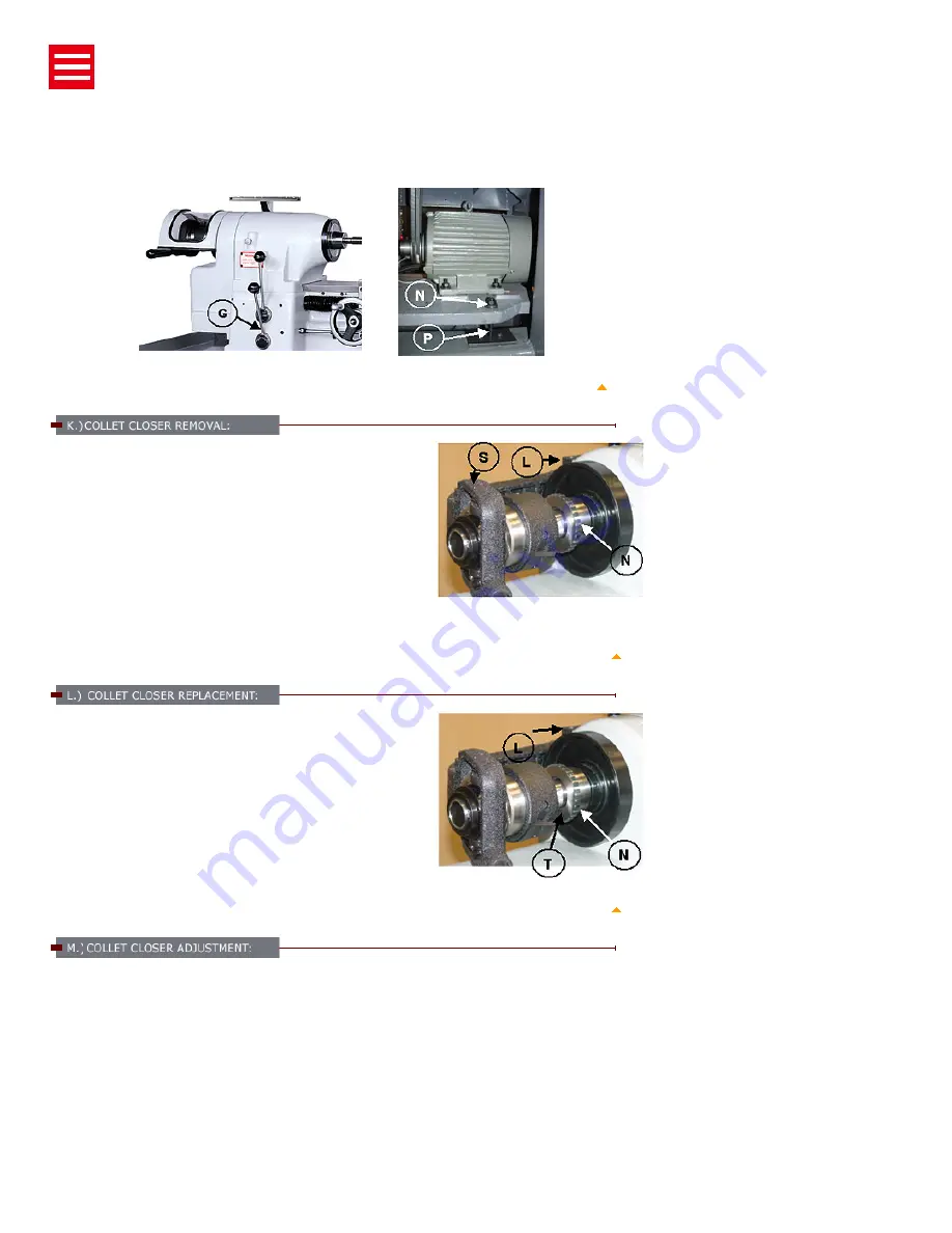
Run spindle at approximately 1000 rpm. Move lever "G" (Figure 21) to center "STOP" position and let the
spindle coast to stop. This is done to equalize belt tension. Loosen lock nut "N" (Figure 22) with 19mm
wrench. Turn adjusting screw "P" (Figure22) with screwdriver clockwise to tighten belts. Stop machine and
check belt tension, there should be approx.1" of play in belt.
Figure 21-Control Speed and Direction
Figure 22-Belt Adjustment
TOP
Running the machine with the collet closer and not having a collet
locked in place will damage the collet closer. Remove the collet closer
when using chucks, face plates, or spindle nose type fixtures. The
collect closer should be removed often for cleaning to prevent loading
of chips between collet closer tube and inside of spindle at rear and
collet threads. Removal method is
:
Pull out pin "L" (Figure 23). Slide
draw tube out of the spindle. Do not turn the adjusting nut "N" (Figure
23). It is keyed to the spindle. To remove slide it off the end of the
spindle. Do not remove collet closer by removing screw "S" (Figure
23), this screw has been adjusted at the factory for proper operation
of the collet closer.
Figure 23-Collet Closer Removal
TOP
Before replacement of the closer, clean inside of the headstock
spindle and outside diameter at rear of spindle where Adjusting Nut
"N" (Figure 24) is located. Apply a film of light oil on rear of spindle Do
not force Adjusting Nut "N" on spindle. If Adjusting Nut "N" fits to tight,
remove and check for burrs or scratches, then replace. Clean collet
closer tube inside and out apply a film of light oil on slip surface "T"
(Figure 24) of the collet closer tube, replace collet loser and insert
Link Pin "L" (Figure 24).
Figure 24-Collet Closer Removal
TOP
1. Before using collet closer, and any collet or step chuck to be used should be thoroughly cleaned.
2. Push the lock Pin "E" (Figure 25). To engage lock pin, turn spindle by hand till lock pin enters notch to
lock.
3. Press the Closer Adjusting Finger "F" (Figure26) down to the point "P" (Figure 26).
4. Guard "G" (Figure 26) forward with the left hand, and hold the collet or stop chuck with the right hand
at the same time.
5. Place a work piece in collet or step chuck.
6. Place lever "L" (Figure 26) to the extreme left fixed position. Turn the Shell Guard "G" (Figure 26)
toward operator until the work piece is clamped by the collet.
7. Place lever "L" (Figure 26) to the right, the released position. Turn Shell Guard "G" (Figure 26) toward
operator, move the Adjusting Finger "F".


