


UM-CV-751-RP-X924-Q221V1 www.austin-hughes.com
P.7
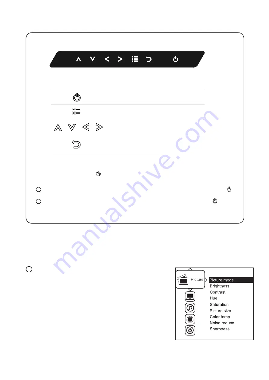
RP-X924
Exit the OSD screen
Go back to the previous on-screen sub-menu or
main menu
Scroll through menu options and adjust
the displayed control
Display the OSD menu
Act as an Enter key to select screen setting options
Turn the monitor on or off
Membrane Switch
Function
Remark : All LED touch buttons in
WHITE
light.
The LED of
Power
touch button will flash continuously when there is no signal input.
All the LED touch buttons will automatically turn off after 10 minutes of idle status ( except the
Power
).
Light up all membrane buttons, please press any button for 1 - 2 seconds ( except the
Power
).
1
2
< 2.2 > On-screen Display Operation ( OSD )
Picture
Picture mode : Standard / Vivid / Soft / User mode to choose
Brightness :
Adjust background black level of the screen image
Contrast :
Adjust the difference between the image background
(black level) and the foreground (white level)
Hue:
Adjust the screen hue value
Saturation :
Adjust the saturation of the image color
Picture size :
Adjust the image size
Color temp :
Standard / Cool / Warm / User to choose
Noise reduce :
Reduce the noise of the image
Sharpness :
Adjust the image from weak to sharp
1


