ECO FUNCTION SETUP
ECO Function
When the ECO function is active the UPS can
detect whether the PC that is connected to the
USB port is turned on or off. If the PC is turned
off, the UPS will turn off the ECO controlled
outlets and cut power to the devices connect-
ed to them in order to save power.
Generally, these are peripherals that are not
used when the PC is not turned on.
ECO Controlled Outlets
Three of the surge-only outlets are also ECO con-
trolled outlets. When the PC that is connected to
the USB port is turned off, the UPS will turn off
the ECO controlled outlets to save energy.
ECO Setup
1. The factory default setting is OFF. ECO mode
can only be enabled/disabled and will only be
active when the UPS is receiving utility power
and not in battery mode.
2. For the EC650/850LCD, press the Mode
switch for approximately 3 seconds to enter
setup mode and select the ECO function. When
the ECO function is selected, press the Mode
switch for 3 seconds to turn the function ON or
OFF. Once ON or OFF is selected, wait 8 sec-
onds for the setting to be confirmed and the
LCD screen will return to status mode. For the
EC450/550/750G, press the ECO button for 3
seconds to turn ON or OFF the ECO function.
3. When the ECO function is OFF, utility power
from the ECO outlets will always be on. When
the ECO function is ON, utility power from the
ECO outlets will turn off if the PC connected
to the UPS via the USB port is turned off or if
there is no PC is connected to the UPS via USB.
ECO Indicator
The LED will blink when the ECO function
is turned ON but the PC is either off or not
connected. The LED will be solid if the ECO
function is turned on and the connected PC is
on. The LED is off when the ECO function is
disabled. See below table for more information.
DEFINITIONS FOR LED INDICATORS & AUDIBLE ALARMS
ECO Indicator
ECO Function
ECO Outlet Status
Condition
Solid (green)
ON
With Utility Power
When PC is ON and USB port on the UPS is
connected, Peripherals will receive power to
operate.
Blinking
ON
Without Utility Power
When PC is OFF or the USB port on the UPS
is not connected, power to the Peripherals will
be turned off.
OFF
OFF
Always with Utility Power
When PC is ON/OFF, Peripherals is always ON.
POWER
ALARM
CONDITION
On
Off
Normal
On
Beep twice
every 30 seconds
Utility Failure - The UPS is providing power to battery power-supplied
outlets from its battery.
On
Rapid beeping
every 1/2 second
Utility Failure - The UPS is providing battery power. Rapid beeping
indicates the unit will run out of power shortly.
On/Off
Constant tone
Battery Overload - Occurs when connected equipment exceeds the
listed capacity of the UPS. Turn the UPS off, unplug at least one piece of
equipment from battery outlets, wait 10 seconds, reset the circuit breaker
and turn the unit on.
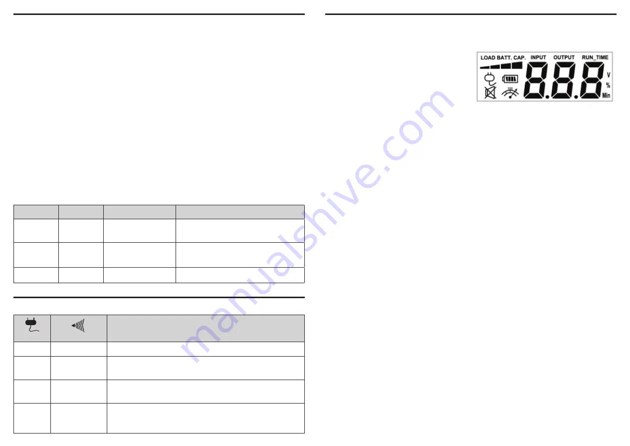
(EC650LCD and EC850LCD only)
INPUT voltage meter:
This meter measures the
AC voltage that the UPS system is receiving
from the utility wall outlet. The UPS is designed
to continuously supply connected equipment
with stable output voltage. In the event of a
complete power loss, extended power reduc-
tion, or over-voltage, the UPS relies on its inter-
nal battery to supply consistent 110/120 output
voltage. The INPUT voltage meter can be used
as a diagnostic tool to identify poor-quality
input power.
OUTPUT voltage meter:
This meter measures,
in real time, the AC voltage that the UPS sys-
tem is providing to the connected equipment
during normal AC/Utility Power mode and
battery backup mode.
ESTIMATED RUNTIME:
This displays the run
time estimate of the UPS with the current bat-
tery capacity and load.
NORMAL icon:
This icon appears when the
UPS is working under normal conditions.
BATTERY icon:
During an extended power re-
duction or power outage, this icon appears and
an alarm sounds (two short beeps followed by
a pause) to indicate the UPS is operating from
its internal battery. The alarm will continue to
sound during a prolonged power reduction or
power outage. The BATT.CAPACITY meter will
show one 20% capacity segment remaining
to indicate the UPS’s battery is nearly out of
power. You should save files and turn off your
equipment immediately.
OVER LOAD icon:
This icon appears and an
alarm sounds to indicate the battery-supplied
outlets are overloaded. To clear the overload,
unplug some of your equipment from the
battery-supplied outlets until the icon turns off
and the alarm stops.
BATTERY CAPACITY meter:
This meter dis-
plays the approximate charge level of the UPS’s
internal battery in 20% increments. During a
power outage or extended power reduction,
the UPS switches to battery power (the BAT-
TERY icon appears) and the battery charge
level decreases.
LOAD CAPACITY meter:
This meter displays
the approximate output load level of the UPS
battery outlets in 20% increments.
DEFINITIONS FOR ILLUMINATED LCD INDICATORS
The LCD display indicates a variety of UPS operational
conditions. All descriptions apply when the UPS is
plugged into an AC outlet and turned on or when the
UPS is on battery.


