background image


The bottom panel 

(Input/output connections) 

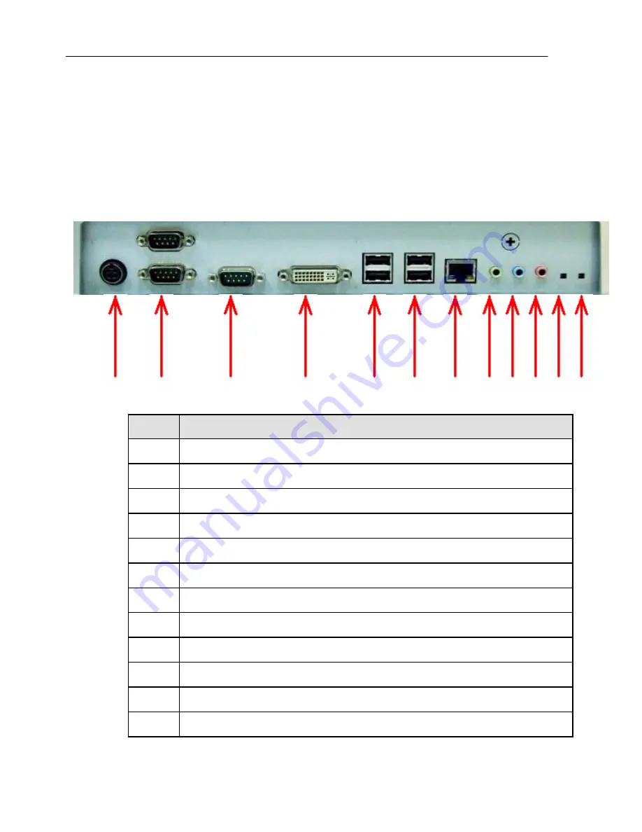
The following picture shows connectors that are for input/output 
connections located at the rear of the main body. Here we provide a 
brief explanation about the name and function of each connection port. 


  1              2,3                        4                          5                        6              7            8            9 10,11 12    13    14


No. 

Connections 

1


DC Power Adapter Input


2,3


Serial ports  COM1, COM2


4


Serial port COM3


5


External Digital (DVI-I) Display device connection


6


USB 2.0 device (1, 2) connection


7


USB 2.0 device (3, 4) connection


8


10/100/1000 Mbps, RJ-45 Ethernet cable connection


9


External speaker or headphone connection


10,11


Audio Line input connection, Optional TV tuner slot   

12


External microphone device connection


13


External system RESET button 


14


External system CLEAR CMOS button


Summary of Contents for i-One 17

Page 1: ...Cybernet Manufacturing Inc i One 17 19 All in One PC Model No LCDPC 945 Version 1 0 V 1 2 ...

Page 2: ...best in drawing up this user s guide there may be omissions and errors we failed to notice Manufacturers and suppliers cannot be held liable for problems stemming from those errors and omissions Registered Trademark Cybernet and Cybernet Manufacturing Inc are trademarks of Cybernet Manufacturing Inc Microsoft Windows XP Windows Vista are registered trademarks of Microsoft Intel Pentium and Celeron...

Page 3: ...e product and do not place heavy things on it z To prevent electric shock and fire do not use an outlet that is damaged or that is not standard z If you plug the power cord into an extension cord be sure that the total voltage of all the devices connected to the cord does not exceed the number specified on it Caution during use z If peripheral equipment is connected to this product turn on the pow...

Page 4: ...s away from this product z Take precautions to avoid losing data stored on the hard disc of this PC and back up important data at all times in case of an unforeseen accident z Do not attempt to disassemble this product When this PC needs repairs or updates request warranty service and have a service person do the work z Should the following situations occur contact one of our quality assurance div...

Page 5: ...e 7 The back side of the main body Security Lock slot 7 Chapter 3 Starting up the computer for the first time 8 For Windows XP or Windows Vista 8 Step 0 Windows XP and basic driver pre setup 8 Step 1 To set up the computer 9 Step 2 The installation of drivers for other peripherals 10 Step 3 The installation of software for other peripherals 11 Step 4 Completion of setup 11 Chapter 4 Using the comp...

Page 6: ...vi Appendix 3 System Block Diagram 28 Appendix 4 System Board 29 Appendix 5 System Dimensions Drawing 30 V 1 2 ...

Page 7: ... devices with its six built in USB 2 0 ports Cybernet s i One supports 802 11 a b g wireless networking using its optional built in miniPCI network adaptor Cybernet s i One also supports videoconferencing with its optional built in CCD WebCam Cybernet s 17 or 19 TFT LCD display directly driven by digital signals offers a clearer image than that of separate TFT LCD monitor of the same class which i...

Page 8: ...ne Quick Users Guide 9 I One Drivers CD Optional devices The following optional devices must be ordered before the product is shipped in order to enable touch screen Wireless networking and videoconferencing and wireless networking 9 17 or 19 Touch Screen Manufacturer ONETOUCH with Touch Kit Software 9 Wireless USB wired Keyboard Optical Mouse Manufacturers Cybernet Manufacturing Inc Logitech Corp...

Page 9: ...tom 9 External speakers headphones jacks 9 External microphones jacks 9 External audio line in jacks 9 External DVI I port For reference z What is USB USB is a high speed serial bus standard for the connection of peripheral devices that reduces the use of valuable system resources Devices that support USB are USB mice USB keyboards USB PC cameras USB HDDs and USB memory sticks V 1 2 ...

Page 10: ...Color Blue LAN Indicates Rx Tx LAN data activity LED Color Green z Button for selecting the on screen display OSD menu item SEL Navigating OSD menu item selection z Button for exiting OSD menu display EXIT de selecting menu item Closing OSD menu display z Buttons for adjusting the built in speakers volume Up Down Adjusts the sound volume of the internal speakers z Buttons for adjusting the built i...

Page 11: ...nts AUTO Auto synchronization of the TFT LCD display z Buttons for displaying OSD menu window MENU OSD menu display The right side of the main body Power Button z Power button Turns the computer on and off z USB 2 0 5 6 device connection V 1 2 ...

Page 12: ... 12 13 14 No Connections 1 DC Power Adapter Input 2 3 Serial ports COM1 COM2 4 Serial port COM3 5 External Digital DVI I Display device connection 6 USB 2 0 device 1 2 connection 7 USB 2 0 device 3 4 connection 8 10 100 1000 Mbps RJ 45 Ethernet cable connection 9 External speaker or headphone connection 10 11 Audio Line input connection Optional TV tuner slot 12 External microphone device connecti...

Page 13: ... Power Adapter Step 1 Insert power cord into power adapter 2 Insert power adapter cable into Power Adapter Input of rear panel 3 Insert power cord into AC power socket The front top of the main body WebCam V 1 2 ...

Page 14: ...7 The left side of the main body Optical Drive The back side of the main body Security Lock slot ...

Page 15: ...ist of operating systems and basic driver files that are pre setup z Microsoft Windows XP or Windows Vista z Intel 945G Chipset driver z Intel 82945G Graphics Media Accelerator driver z Realtek ALC202A Audio driver z Realtek RTL8169 8110SC PCI Fast Ethernet NIC driver z Microsoft DirectX runtime software z Acer OrbiCam Camera Software option z VIA VT6655 miniPCI Wireless LAN driver option z Touch ...

Page 16: ...mes with the purchase of this PC and select Next 5 A dialog box will appear asking you to designate a computer name Enter a computer name and computer description in the blanks and click Next 6 A dialog box will appear asking you how you want to connect to the Internet Select the one that best suits your connection and press Next If your computer is not connected to a network or failed to establis...

Page 17: ...d press Next To proceed to the next step you have to enter at least one name 10 When a dialog box that reads Thank you pops up this means the basic setup is complete Press Finish to reboot your computer and to run Windows XP Step 2 The installation of drivers for other peripherals Skip this step if you do not use other peripherals To use other peripherals this PC supports such as printers serial c...

Page 18: ...n devices USB devices and game consoles MIDI devices install the appropriate software e g utilities or other applications provided by the manufacturer of the device following the instructions displayed on the setup menu and referring to the user s guide Step 4 Completion of setup When you are finished with step 3 basic installation is complete and the computer is ready to use once it is rebooted ...

Page 19: ...Vista Help and Support Center provides the following information on a variety of features and other basic operations of Windows XP Vista z What s new in Windows XP Vista Confirmation of license and registration Windows components z Music video games and photos z Windows Basics z Networking and the Web Electronic mail and the Web Home network or small scale network The sharing of files printers and...

Page 20: ...13 Using other applications To use other applications obtained or purchased separately refer to the user s guide of each application provided by the software manufacturer ...

Page 21: ...w device However if the BIOS CMOS utility setup is wrongly configured a serious system error can take place such as unable to boot the system so be c areful when changing the settings For reference BIOS CMOS setup refers to setting up the components of the system hardware and saving them The settings are saved even when the power is off because the settings are stored in CMOS RAM built into the sy...

Page 22: ...anced BIOS Features Advanced Chipset Features Integrated Peripherals Power Management Setup PnP PCI Configurations PC Health Status Frequency Voltage Control Load Fail Safe Defaults Load Optimized Defaults Set Supervisor Password Set User Password Save Exit Setup Exit Without Saving Esc Quit Select Item F10 Save Exit Setup Time Date Hard Disk Type ...

Page 23: ......

Page 24: ...nt Setup You can set up the power mode PnP PCI Configurations You can set up PnP PCI configuration including IRQ settings PC Health Status You can check the condition of the computer CPU system temperature cooling fan temperature Frequency Voltage Control You can control the clock and voltage of the CPU Load Optimized Defaults You can change every CMOS setting to the defaults set before shipping S...

Page 25: ... on the right side of the screen To enter a sub menu Press Enter Topics with means there are sub menus To shift to main menu from sub menu Press Esc To return to the default setting Press F7 To save changes to the settings and exit Press F10 5 To save all the modifications in CMOS RAM and exit the setup press F10 When a dialog box reconfirming the modifications appears select Y The system will reb...

Page 26: ...meet the user s growing needs so please upgrade to the latest version for major software that i s already installed on this PC on a regular basis at the following sites z Windows XP Vista http windowsupdate microsoft com Default htm z Basic driver files Intel drivers Realtek drivers Cybernet website or Drivers CD provided with your unit BIOS Upgrade With this PC you can upgrade BIOS using the BIOS...

Page 27: ...m for Windows 1 First obtain an upgraded BIOS file from Cybernets Customer Support Center and BIOS flash utility program for Windows WinFlash exe Winflash sys located on the Drivers CD provided with your product 2 Move to the directory where the downloaded file is located and execute the BIOS flash utility program WinFlash exe 3 Update BIOS following the instructions displayed on the execution scr...

Page 28: ...e computer The Windows Setup screen will appear automatically starting the installation 2 Continue installing the Windows XP Vista following the instructions displayed on the screen 3 When installation is complete the computer will restart running Windows XP Vista and the desktop will appear Insert the I One Drivers CD in the optical drive Choose each driver and application from the automatic exec...

Page 29: ...ware screen in System registration information Here click Device administrator to check whether each device is working properly If the yellow exclamation mark is in front of the device s name or if the name of the device is not displayed this means the pertinent device is not functioning normally or it is not properly installed In this case users have to update or reinstall the driver for that dev...

Page 30: ...isk is not being read properly contact the Customer Support Center Error message CMOS checksum error appears when booting This can occur when the motherboard s CMOS backup batteries have run out Contact the Customer Support Center to replace the batteries Booting to safety mode 1 This can be caused when the computer was not properly shut down Click Start End to shut off the computer and reboot 2 T...

Page 31: ...located at the rear of the unit The USB cable must be connected to the USB port 2 When the system is down this may occur Restart the computer and check whether the keyboard is working USB device is not working 1 If the USB device manufacturer provides the driver install the driver first and restart the computer 2 Disconnect the USB device and then reconnect it and check if it works properly Re exe...

Page 32: ...this symptom should repeat contact the Customer Support Center The computer suddenly freezes wile in use 1 This may be caused by an error in a program Press Ctrl Alt Del and click on End now on the Windows Task Manager dialog box 2 This can be caused by an error in Windows Restart the computer by pressing the power button for more than four seconds V 1 2 ...

Page 33: ...rial ATA controller facilitates One 3 5 SERIAL ATA Hard Disk for high speed data transfers of up to 150 MB s VIDEO GRAPHICS Intel Graphics Media Accelerator 950 Stunning media incredible visuals and new 3D capabilities For business users Intel validates the chipset processor graphics and software stack to provide a well tested platform with support for Microsoft Windows Vista Windows XP Linux top ...

Page 34: ...CPI API DMI Plug Play and security password Supports booting from HDD PXE LAN CD ROM and ANY USB device LED INDICATORS HDD LAN Activity POWER SUPPLY Uses 180Watt AC Adapter Input universal 100 240V AC 50 60Hz Output 19V DC 9 48A Controlled by Dual Mode Power button on the keyboard Low power sleep mode saves energy BIOS SECURITY Award BIOS System POST and BIOS setup password protection SECURITY LOC...

Page 35: ...RELATIVE HUMIDITY 10 90 non condensing AVAILABLE COLORS Silver Black White ...

Page 36: ...28 Appendix 3 System Block Diagram V 1 2 ...

Page 37: ...System CLEAR CMOS micro switch 7 1GbE RTL8169 LAN chip 8 PCI e bus slot 9 32 bit miniPCI socket 10 Front Panel Board connector 11 ITE Super IO chip 12 2 x USB 2 0 port connector 13 AWARD BIOS chip 14 WebCam USB connector 15 Intel 945G Southbridge chipset 16 SATA HDD data cable connector 17 IDE Optical Drive connector 18 DDR2 SODIMM sockets 19 HDD Power cable connector 20 LCD Panel Inverter card co...

Page 38: ...30 Appendix 5 System Dimensions Drawing V 1 2 ...

Page 39: ......

Reviews: