background image

!

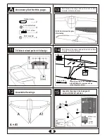
Accessory list for this page.

13

12

15

14

5

5

11

B

B

A

A

Carbon tube

 - - - - 2

 - - - - 2

8.2mm

M5X65mm  screw

Wing

Fuselage

M5  nut

M5X60mm   screw

- - - - - - 4

5mm   washer

- - - - - - - - - - - 4

5mm  Blind Nut

       - - - - - - - - - 4

8.2mm

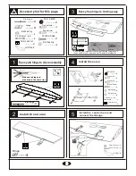
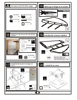
Assemble the wings

Drill 8.2 mm holes at the place
of main wing

Install the wing to the fuselage
with M5X60mm screws as shown
in the diagrams below.

A = A1

Drill holes in the wings and set the Carbon fibre 
 dowels in them as below

Drill holes in the wings and set the Carbon fibre 
 dowels in them as below

Drill holes to relevant position in the fuselage

Assemble the wings to the fuselage with
screw  and blind nut as below

5

5

Carbon tube

 - - - - 2

M5X65mm   screw

- - - - - - 4

5mm   washer

- - - - - - - - - - - 4

5mm  Blind Nut

       - - - - - - - - - 4

70

70

4

1

2

m

m

7

2

5mm

Summary of Contents for Reggiane RE 2005

Page 1: ...model You are responsible for this model s assembly and safe operation lAlways keep this instruction manual ready at hand for quick reference even after completing the assembly lCould cause serious injury or even death SPECIFICATION Reggiane RE 2005 Thank you for choosing CYmodel Global www cymodel com Australia www austars model com Italia www biellaexpress com Instruction Manual Wing Span 2400 m...

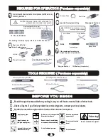
Page 2: ...mm 2mm Assemble left and right Sides the same way Apply instant glue CA glue super glue Apply epoxy glue B A Cut off excess Do not overlook this symbol 1 1 A minimum 6 channel radio for airplanes with 8 servos And dry batteries CAUTION Only use a minimum 6 channel radio for airplanes No other radio may be used 12 AA size Batteries A minimum 6 channel transmitter for airplanes 2 2 For handing the r...

Page 3: ...flights you ll lose control of your airplane which leads to accidents Warning Warning Flap Aileron Tailing edge Aileron 2mm Rod adjuster 2 5X85mm rod 4 4 Rod adjuster 4 4 4 Ball bearing Ball bearing 3mm washer 4 3X16mm Screw 4 3mm Lock nut 4 8 Pin hings Hinge Rod adjuster 2 5X85mm rod 4 4 Rod adjuster 4 4 Ball bearing Ball bearing 3mm washer 4 3X16mm Screw 8 3mm Lock nut 8 8 HORN 8 3X16 Screw 4 3m...

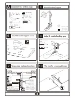
Page 4: ...t 2 2 3X3mm screw 4 M3X5mm Screw 4 2 3mm plywood 2 3mm plywood Mount the landing gear cover Pleas notice the inner diameter for each side of the pressure reduction inlet Please insure the sealing of the retract system before flight Retainer Rod adjuster 2X8mm screw 1 1 1 Rod 1 8X80mm 1 2000mm Air line 2 Quick release connector 3 way pressure inlet 3 way pressure inlet Air inlet Switch Air tank Air...

Page 5: ...ng Install the wing to the fuselage with M5X60mm screws as shown in the diagrams below A A1 Drill holes in the wings and set the Carbon fibre dowels in them as below Drill holes in the wings and set the Carbon fibre dowels in them as below Drillholestorelevantpositioninthefuselage Assemble the wings to the fuselage with screw and blind nut as below Carbon tube 2 M5X65mm screw 4 5mm washer 4 5mm Bl...

Page 6: ...A Ply wooden B A Warning Securely glue together if coming off during You will lose control of your airplane which leads to accidents Assemble the elevator to stabilizer Epoxy pin hings to elevator B A Install the servo 4 Ply wooden M4x12mm Screw 3X3mm Screw 4 4 3 Pin hings Drill holes in the belly pants appropriate position Assemble the belly pants to the wings with screw Hardwood 4 Hardwood 4 ...

Page 7: ... 2 3mm Lock nut 2 2 3x10mm Tp Screw 8 The position of the control horn in the elevator A B B B B1 B1 B B1 A B AWL AWL Secure the servo Install the nylon control horn and connect the linkage Assemble the stabilizer to fuselage as illustration Assemble the stabilizer to fuselage as illustration HORN 4 2 3x10mm Tp Screw 8 Rod adjuster 2 5X85mm rod 2 2 Rod adjuster 2 2 2 Ball bearing Ball bearing 3mm ...

Page 8: ...gether if coming off during You will lose control of your airplane which leads to accidents B A Aluminium tube Rod Steel wire Rod adjuster HORN 3X16 Screw 2 2 2 2 3mm Lock nut 2 2 2 2 A B Assemble the stabilizer to fuselage as illustration 3 Pin hings Aluminium tube Rod Steel wire Rod adjuster HORN 3X16 Screw 2 2 2 2 3mm Lock nut 2 2 2 2 Rudder Connect the linkage rod to the horn Rudder Connect th...

Page 9: ...Screw 4 M5x65 screw 3mm plywood Hardwood After confirming the position see front of fuel tank Insert and tighten the screw 3X20mm Screw 1 1 Assembly of the full tank Assembly of the engine Assemble the tail landing gear to the fuselage Fitting of the tail wheel assembly 1 3 3 2mm Collar 3 2mm Nylon Collar 3X3mm Screw 3 6X9 screw 1 1 6mm nut 3 2mm Rocker 1 Aluminium tube Rod adjuster 2 Rod 2 2 Stee...

Page 10: ...screw M3X15mm screw 3mm Washer 5 5 3mm plywood 10 3mm Blind Nut 5 2 3X10 Tp screw 6 B A Assemble the antenna to fuselage with A B glue Assemble the canopy to the fuselage with TP screws Assemble the cowling to fuselage with screw Assemble the oil filler pipe to fuselage withA B glue Rod adjuster 2 Rod 2 Aluminium tube 2 2 3X10 Tp screw 6 M3X15mm screw 3mm Washer 5 5 3mm plywood 1 3mm Blind Nut 5 ...

Page 11: ...ing to your needs and flight level Never fly before checking the Cg s required position In order to obtain the CG specified reposition the receiver and battery NEVER fly the model without well balancing Warning 41 AILERON Adjustment Top view Adjust the travel of each control surface to the values in the diagrams These values fit general flight capabilities Readjust according to your needs and flig...

Reviews: