background image

15

INITIAL SET UP AND PLC RESET

Initial Setup

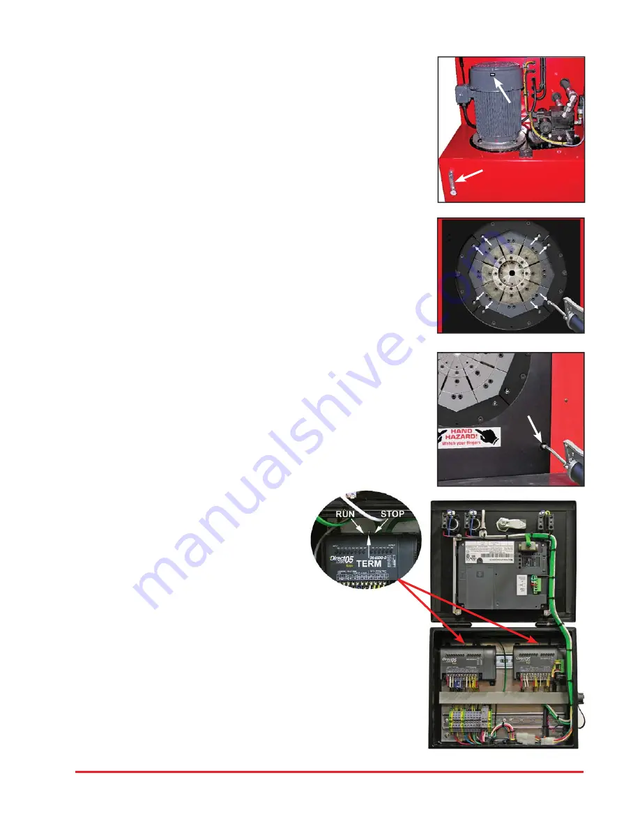
Check to be certain that the motor rotates in the direction of the arrow shown 
on the motor housing.  If motor rotation is opposite of the direction of the 
arrow, reverse any two hot wires in the electrical plug.

Damage to the pump can result if the motor does not rotate in the correct 
direction.

Check the oil level in the sight glass on the front of the tank. 50 U.S. gallons 
of ISO 46 hydraulic oil are required to completely refi ll the tank.

Oil can be drained from either of the two ports at the bottom of the tank.

An additional oil cooler, while not normally required, can be plumbed into the 
two ports at the rear of the tank.
 

Lubrication

Lubricate the crimping head after each 400 crimping cycles or at the start of 
each shift if the crimper is used in a production setting.

Bring the master dies to the fully closed position, and lubricate the master 
dies through the 8 holes in the protective plates as illustrated.

With the dies still in the fully closed position lubricate the fi ttings visible through 
the 2 bottom lubrication holes in the protective plate of the crimper.

Use only a high quality grease.  Failure to do so may result in damage to the 
wearing surfaces.

PLC Reset Procedure

The PLC (Programmable Logic Controller) requires a 
relatively constant source of electrical power.  Power 
surges, outages or drops in power can cause the PLC 
to lose its settings.  This may result in missing or 

misplaced information on the controller screen

.

Resetting the PLC to its original 
settings is a simple procedure

•  Turn the main power switch to OFF.              

•  Open the front of the Control Panel.

•  Power up the crimper from the main power switch.  The crimper must be 

powered on during the PLC reset procedure.

•  Move the three position toggle switch on top of the PLC right to the STOP 

position and then left to the RUN position.

•  Return the toggle switch to the center TERM position.

•  Repeat for the other PLC Unit.

•  Turn the main power switch to OFF and replace the front panel.

•  The PLC and the crimper should now operate normally.

Summary of Contents for CC1000

Page 1: ...1 CC1000 CRIMPER OPERATORS MANUAL WITH ACTTM CONTROLLER ...

Page 2: ... PRECAUTIONS READ INSTRUCTIONS AND IDENTIFY ALL COMPONENT PARTS BEFORE USING CRIMPER KEEP HANDS AWAY FROM PINCH POINTS CONSULT HOSE AND FITTING MANUFACTURER S SPECIFICATIONS FOR CORRECT MACHINE SETTINGS AND CRIMP MEASUREMENTS ALWAYS WEAR EYE PROTECTION CC1000 Crimper Operators Manual With ACT Controller Revised 03 28 2016 For Parts and Service Contact Custom Machining Services Inc Valparaiso In 46...

Page 3: ... 99mm Adapter Dies 99mm Hydraulic Dies Hydraulic Power Unit and Controls 145mm to 99mm Adapter Die Hydraulic Die 230mm to 145mm Adapter Die Master Die 230mm to 145mm Adapter Dies Return Hose Adjustable Mirror Hydraulic 99mm Die Storage Pockets Industrial Die Storage Shelves Pressure Hose ...

Page 4: ... MM AND 145 MM TO 99 MM HOSE CAPACITY 2 1 2 INCH 6 SPIRAL 10 INCH INDUSTRIAL INITIAL CRIMPER SET UP CHECK RESERVOIR OIL LEVEL WITH SIGHT GLASS ON THE FRONT OF THE POWER UNIT CHECK ELECTRICAL CIRCUIT TO BE CERTAIN THAT IT MATCHES THE CRIMPER REQUIREMENTS AS SHOWN ON THE TAG ATTACHED TO THE CRIMPER CORD MAKE CERTAIN THAT MOTOR ROTATES IN THE DIRECTION OF THE ARROW SHOWN ON THE MOTOR HOUSING IF MOTOR...

Page 5: ... CONTROL PANEL U S Patent No 7 383 709 NOTE IF THE CRIMPER IS IN MANUAL MODE THE GREEN OPEN CLOSE BUTTONS WILL OPEN AND CLOSE THE CRIMPER HEAD IF THE CRIMPER IS IN AUTO MODE THE BUT TONS FUNCTION AS CYCLE START AND CYCLE STOP BUTTONS IF THE CRIMPER IS IN SEMI AUTO MODE PRESSING THE FOOT SWITCH OR THE CLOSE BUTTON WILL CLOSE THE CRIMPER HEAD AND RELEASING WILL HALT THE CLOSING ACTION ...

Page 6: ...es for a 1 5 inch die enter 1500 ACTTM will add 3 decimal places Enter the finished crimp diameter and press ENTER From the ENTER CRIMP screen press the MANUAL button to put the crimper in manual mode Confirm that the die and finished crimp diameters are correct and that MANUAL MODE is displayed Press and hold the green close button until the crimper stops closing Check the final crimp diameter If...

Page 7: ...r of the fitting in either inches or mm Do not enter the amount of correction and press ENTER Press SAVE Make another crimp and verify that the fitting is within specifications EXAMPLE If the hose and fitting manufacturer specifies that the finished crimp should measure 1 500 to 1 520 and the measured crimp diameter was 1 530 simply enter the measured diameter 1530 Controller will supply 3 decimal...

Page 8: ...description up to 12 alpha numeric characters Enter diameter units inch or metric Enter the closed diameter of the die Press SAVE and EXIT The saved die will now appear on the SELECTED DIE screen From this screen individual dies can be cleared or edited HOW TO RECALL A SAVED DIE Select CRIMP TO DIAMETER and from the OPTION screen select USE SAVED DIE Select the saved die 1 50 and press LOAD and th...

Page 9: ...ion 1 150 and press EDIT Enter a description up to 12 characters Press SAVE and EXIT The die and crimp setting can now be recalled from the saved location as required TO RECALL SAVED CRIMP Select USE SAVED CRIMP from the option screen Select a previously saved crimp from location 1 150 Press LOAD The saved crimp will appear on the manual screen ...

Page 10: ...o position allowing more precise positioning of a fitting in the dies Pressing the SEMI AUTO button will toggle the crimper back to FULL AUTO mode In FULL AUTO mode pressing the foot switch will start the crimp cycle and the dies will stop closing when the crimp cycle is complete The COUNT function is activated allowing the operator to monitor the number of crimps made A measurement can be require...

Page 11: ...l features and functions of the ACTTM controller can be accessed by pressing the MORE button on the MACHINE SET UP screen When Allow Crimp to Diameter is set to YES all of the adjustment functions of the crimper are available When Allow Crimp to Diameter is set to NO only the settings entered as a saved crimp can be used English or Spanish language options are available The Use Pressure Compensati...

Page 12: ...specifications or if they are available to you they are accessed in the following manner Press the Crimp Memory Table Button Press the access button to bring up the stored crimp specifications Scroll through the crimp specifications to select the correct one The right hand rocker button moves through the crimp specs one line at a time and the left hand rocker button moves one screen at a time When...

Page 13: ...s the right arrow and take 2 more measurements of the hose wall thickness The Industrial Crimp Calculator will average the three measurements Enter the stem diameter of the fitting For example If the stem diameter is 4 inches you would enter 4000 and the ACTTM controller would supply the decimal place Measure and enter the wall thickness of the ferrule Next enter a compression factor While this can...

Page 14: ... the face of the die should face toward the operator Align the studs of the Hydraulic Dies with the holes in the Adapter Dies and with the crimper in manual mode SLOWLY close the crimper head on the die set Bring the crimper head to a fully closed position and remove the die insertion tool The dies may also be inserted manually with the crimper head in the fully open position Proceed to the ACTTM ...

Page 15: ...in the protective plates as illustrated With the dies still in the fully closed position lubricate the fittings visible through the 2 bottom lubrication holes in the protective plate of the crimper Use only a high quality grease Failure to do so may result in damage to the wearing surfaces PLC Reset Procedure The PLC Programmable Logic Controller requires a relatively constant source of electrical...

Page 16: ...rvice Check motor rotation and be certain that the motor rotates in the direction of the arrow on the motor housing For three phase units rotation can be reversed by switching any two wires in the plug PROBLEM CRIMPER WILL CLOSE ON FITTING BUT DOES NOT DEVELOP POWER TO COMPLETE THE CRIMP Check oil level Position dies to the fully open position and check oil sight gage in rear of machine Be sure th...

Page 17: ...TECTIVE SLIDE PLATE 103209 2 1 CC1000 BACK PANEL 103214 3 2 CC1000 PROTECTIVE PLATE WRAP 103236 4 1 CC1000 TOP FRAME WRAP 103219 5 24 M6 X 12 BHCS 91239A318 6 2 M6 X 16 BHCS 91239A321 7 15 99S DIE HOLDER 101242 8 60 1 4 20 x 3 4 SHCS 91251A540 9 2 CC1000 BASE LEG 103208 10 8 M12 X 50 SHCS 91290A626 11 5 4 2 3 6 7 1 8 9 6 2 10 6 ...

Page 18: ...M10 X 20 FHCS 91294A328 4 2 CC 1000 STATIONARY WEAR PLATE 103163 5 8 M6 X 25 FHCS 91294A242 6 1 CC 1000 CYLINDER ASSEMBLY 103158 7 1 M16 X 70 SHCS 91290A837 8 2 CC1000 LEFT SUPPORT LEG ASMB 103206 L 9 2 CC1000 RIGHT SUPPORT LEG ASMB 103206 R 10 8 M12 X 50 SHCS 91290A626 11 8 M12 WASHER 91166A290 12 1 2 3 5 6 4 8 7 11 12 9 10 TORQUE TO 305 FT LBS EXPLODED PARTS VIEW ...

Page 19: ...103248 7 2 M12 X 50 SHCS 91290A626 8 1 M16 X 50 SHCS 91290A820 9 4 CC1000 PROTECTIVE PLATE ALIGNMENT TABS 103230 10 1 CC600 1000 ROLLER LIMIT SWITCH 103473 11 1 CC600 1000 ADJUSTABLE BRACKET 103349 12 4 CC1000 PROTECTIVE PLATE KEY 103448 13 1 CC600 CC1000 LINEAR POTENTIOMETER 103472 14 2 10 24 x 5 8 SHCS 91251A244 15 2 10 24 X 3 4 SHCS 91251A345 16 2 10 24 ROUND WASHER 91255A549 17 4 M4 X 25 SHCS ...

Page 20: ...PTION PART NUMBER ITEM 4 CC1000 MASTER DIE CARRIER 103147 1 40 CC1000 MASTER DIE ALIGNMENT NUT 103249 2 40 M4 X 10 SHCS 91290A144 3 8 M8 X 45 SHCS 91290A446 4 8 CC1000 MASTER DIE SHOE 103156 5 24 DIE SPRING 103470 6 2 M10 X 100 SHCS 91290A548 7 4 1 5 3 2 6 7 3 2 ...

Page 21: ... 1 CC1000 SHEET METAL WRAP 103219 1 4 CC600 1000 MIRROR BRACKET SUPPORT ARMS 103307 2 1 CC600 1000 MIRROR ATTACHMENT BRACKET 103345 3 1 12 X 12 MIRROR 103471 4 2 M12 X 40 BHCS 91239A620 5 2 3 8 16 X 1 BHCS 91255A624 6 2 3 8 16 HEX NUT 94846A031 7 2 3 8 16 X 1 1 4 BHCS 91255A626 8 2 3 4 5 1 7 6 8 ...

Page 22: ... 3 4 4 10 24 X 1 2 BHCS 91255A242 5 4 1 4 20 x 3 4 BHCS 91255A540 6 1 1 2 13 LOCKING HANDLE KHA 150 7 1 1 4 20 LOCKING HANDLE KHA 108 8 1 6 TOUCH SCREEN TEXT PANEL 102600 9 1 1 2 NPT DOME CORD GRIP 69915K53 10 2 ROMEX CORD GRIP 69915K51 11 1 3 4 NPT DOME CORD GRIP 69915K57 12 1 FOOT PEDAL JACK W NUT 502 N 111 13 2 CLOSE OPEN BUTTON E22PB3A 14 1 EMERGENCY STOP BUTTON E22LLB2B 15 1 USB CONNECTOR PX0...

Page 23: ...ydraulic product to ATTN WARRANTY REPAIR DEPT Custom Machining Services Inc 326 North Co Rd 400 East Valparaiso IN 46383 If any product or part manufactured by Custom Crimp is found to be defective by Custom Crimp at its option Custom Crimp will either repair or replace the defective part or product and return via ground transportation freight prepaid Custom Crimp will not cover any incoming or ou...

Page 24: ... CustomCrimp Crimpers and Accessories at 219 462 6128 CustomCrimp www customcrimp com Custom Crimp Custom Machining Services Inc 326 N County Rd 400 East Valparaiso IN 46383 Ph 219 462 6128 Fax 219 464 2773 www customcrimp com ...

Reviews: