


General Installation
Thank you for your purchase of this Custom Autosound product!
Owner- Installer: Please review installation instructions and owners manual.
Keep in mind that your radio and/or speakers are custom equipment designed specifi-
cally for your year vehicle. It should be handled carefully and installed preferably by an
auto radio specialist. We suggest that you 'Bench Test" the unit before installation, as
we do, prior to shipment.This is to insure that the equipment functions properly before
the time is spent for installation. This way, if a careless installation occurs and the unit
becomes "fried" or some other possible damage,the installer is responsible. Shipping
damage does occasionally occur. If you should suspect shipping damage, please con-
tact the delivery company at once.
Please read the owners manual thoroughly before using your radio.
It is recommended that you disconnect the negative lead from the battery before
installing any electronic equipment in your vehicle. Reconnect when wiring is complete.
First, you will need to remove the original knobs, bezels and shaft nuts. Unplug the
main wire harness and speaker leads from the back of the radio. Disconnect antenna
lead and remove mounting strap from the back of the radio. The radio is now ready to
be removed from the dash. Check the original radio for signs of water or oil damage
from leaks. If leaks are present, do not install the new radio. Water, oil or any other liq-
uid damage is not covered under the new radio warranty.
REAR MOUNTING STRAP OMISSION VOIDS WARRANTY!
Attach the rear mounting strap to rear of radio. Install the radio from behind the dash.
Now attach the mounting strap to the dash or firewall using an existing bolt or screw.
Now install any outer custom trim bezel, if one was furnished for this application and
attach shaft nuts to secure the radio in the dash. Once the radio is centered and
secured, you can install the knobs.
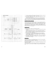
Please refer to wiring instructions on page 4&5.
Plug in antenna lead On speaker hook up make sure the positive lead goes to the posi-
tive terminal and the negative lead to the negative terminal of the speakers. A minimum
of two speakers are required for this stereo radio. DO NOT CONNECT ANY TWO
SPEAKER LEADS TO EACH OTHER OR TO VEHICLE GROUND. Radio damage will
occur. If less than four speakers are used, tape off remaining speaker leads to prevent
a short.
Plug in or wire the red power wire to a switched 12volt source. Plug in or wire the
orange memory wire to a constant 12volt source. Wire the black ground wire to a clean,
solid chassis point or original ground wire from the factory radio.
Good Listening! Audio quality is only as good as speaker quality!
3
12
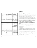
Antenna Noise
A static or crackle heard through the speakers, usually when the car is running ,but
sometimes present with the ignition off. If a crackling static if present, follow the steps out-
lined below to confirm the antenna as the source of the noise.
1.
Start the car engine.
2.
Switch on the USA-1.
3.
Adjust the volume so that noise is audible.
4.
Reduce volume setting of the car stereo but do not switch it off. If noise
decrease
.
or disappears, the signal is most likely being picked up by the
car antenna. If the noise persists after following the steps listed below,
proceed to ignition Noise.
Elimination
1.
Test or have tested the antenna lead for any breaks or shorts. Signs of crimping,
kinking fraying or rust usually indicates damage to the cable. Replace the
antenna or cable if necessary.
Ignition Noise
A popping or crackling noise heard through the speakers. The noise will vary as the
engine rpm varies,The noise will Only be present with the engine running
Elimination
1.
Install an L.C. Filter Network in the power lead of the USA-1. The filter should
be rated at a minimum of 3 amps.
2.
Inspect spark plug and distributor cable for signs of wear or damage. Replace
as necessary using resistor cable only. Metal conductor ignition cables
increase static interference.
NOTE: Do not use spark plug or distributor noise filters as these can create more prob-
lems than they can solve. They decrease the quality of the spark generated by the spark
plugs and they may create more static than they eliminate.
Accessory Noise
A popping heard when the lights, turn indicators, windshield wipers, cigarette lighter, etc.
are switched on indicate a vehicle wiring deficiency. Most occurrences are minor and pre-
set no risk to the stereo system other than the annoyance to the listener. However, severe
cases may damage the speakers, minor occurrences can be remedied. A professional
must attend to severe occurrences, as they present a threat to not only the stereo system
but to the vehicle wiring itself.
Elimination
1.
Install an L.C. Filter Network in the power leads of the USA-1. The filter should
be rated at a minimum of 3 amps.
2.
If the noise persists, consult a professional automotive service technician.


