background image

5.4  Thermistor

The thermistor is very important to adjust the strobe time (Tstrobe) ~ (SLT) in function of the head temperature and to moni-

tor the temperature to prevent the head damage if the substrate temperature is over the limit of 70 °C .

• 

Resistance R25: 

30 kΩ ± 5% at 25 °C

• 

β value: 

3950 K ± 2%

•  Operating temperature: 

– 40 ~ + 125 °C

•  Time constant: 


0 .5 s (in the air)

Then the resistance value, R, versus temperature, T (in °C) is given by the formula:

R(T

X

) = R25 × EXP [ β × (1/TX – 1/T25) ]

Fig. 5.4.1 Thermistor curve

0

200000

400000

600000

800000

1000000

1200000

1400000

-4

0,

00

-3

5,

00

-3

0,

00

-2

5,

00

-2

0,

00

-1

5,

00

-1

0,

00

-5

,0

0

0,

00

5,

00

10

,0

0

15

,0

0

20

,0

0

25

,0

0

30

,0

0

35

,0

0

40

,0

0

45

,0

0

50

,0

0

55

,0

0

60

,0

0

65

,0

0

70

,0

0

75

,0

0

80

,0

0

85

,0

0

90

,0

0

95

,0

0

10

0,

00

10

5,

00

11

0,

00

11

5,

00

12

0,

00

12

5,

00

R

es

is

ta

nc

(K

O

hm

)

Temperature (°C)

22
Summary of Contents for MT2480

Page 1: ...USER MANUAL MT2480 ...

Page 2: ......

Page 3: ...tial switch Before any type of work is done on the machine disconnect the power supply Use the type of electrical power supply indi cated on the device label These devices are intended to be powered by a separately certified power module hav ing an SELV non energy hazardous output IEC60950 1 second edition Only POS equipment The energy to the equipment must be provided by power supply approved by ...

Page 4: ......

Page 5: ...AD 17 5 1 Block diagram of the electrical circuit 17 5 2 Printing data and printing position 18 5 3 Electrical characteristics of circuit 19 5 4 Thermistor 22 5 5 Operation precautions 23 6 STEPPER MOTOR 25 6 1 Excitation sequence Full Step 25 6 2 Precautions 25 7 SENSOR 27 7 1 Graphics of typical characteristics 28 8 SPECIFICATIONS 33 8 1 Hardware specifications 33 8 2 Device dimensions 36 9 CONS...

Page 6: ...6 ...

Page 7: ... the autotest routi ne and prints out the Setup report The printer permits the configuration of default parameters CCCC During power up if the LF LINE FEED key is held down the printer enters the auto test routine and prints out the Setup report The printer permits the configuration of default parameters Numbered title for chapter Numbered title for paragraph Information valid for devices AAAA BBB...

Page 8: ...8 ...

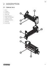
Page 9: ... 1 External view 1 Motor 2 Printhead 3 Head up lever 4 Platen roller 5 Sensor for head up 6 Platen roller manual feed 7 Printhead connector 8 Paper presence sensor 9 Paper input 10 Paper outfeed 1 3 6 8 4 7 2 5 10 9 9 ...

Page 10: ...2 2 Product label PC Product code 14 digits SN Serial number HW Hardware release XXXXXXXXXXXXXX Rx 0000000000000000000 HW PC SN 10 ...

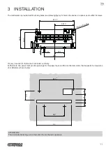
Page 11: ... 0 1 2 3 0 1 0 1 40 3 0 1 0 1 46 5 0 1 0 1 2 8 M2 5 n 4 thread It s very important to fasten the mechanism vertically Furthermore the panel must provide openings for the paper input and the mechanism motor that respects the measures in millimeters shown below 86 7 9 5 50 0 1 0 1 85 1 0 1 0 1 13 14 7 21 5 ATTENTION The horizontal fastening can compromise the mechanism operation 11 ...

Page 12: ...12 ...

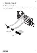
Page 13: ...inals The mechanism has three interface connectors see following figure that includes the thermal head connector motor connector and paper control connector 1 15 Thermal head connector 6 1 Paper control connector 4 1 Motor connector 13 ...

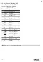
Page 14: ...er supply 2 Vset Head power supply 3 Vset Head power supply 4 GND Ground 5 GND Ground 6 GND Ground 7 VDD Logic power supply 8 TM Thermistor 9 STB1 Strobe1 signal Active low 10 STB2 Strobe2 signal Active low 11 STB3 Strobe3 signal Active low 12 STB4 Strobe4 signal Active low 13 CLK Serial clock 14 LATCH Latch Active low signal 15 DI Data input NOTE The symbol means a negative logical signal 14 ...

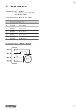
Page 15: ...hite terminal 50058 8000 The connector s pin assignments is as follows J7 MOTOR CONNECTOR No SIGNAL FUNCTION 1 MOT1A Phase A coil 2 MOT1B Phase B coil 3 MOT2A Phase A coil 4 MOT2B Phase B coil Electrical circuit block diagrams of motor 1 3 2 4 MOT1A Motor A B MOT2A MOT1B MOT2B 15 ...

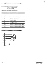
Page 16: ...is as follows J9 MECHANISM SENSOR CONNECTOR No SIGNAL FUNCTION 1 C Collector photo transistor paper 2 E Emitter photo transistor paper 3 A LED Anode paper 4 K LED Cathode paper 5 SW1 Switch signal 1 of head up sensor output 6 SW2 Switch signal 2 of head up sensor output Electrical circuit block diagrams of mechanism sensor 3 C E A 1 2 4 5 6 SW1 SW2 K 16 ...

Page 17: ... VALUE UNIT Rave Average resistance 800 Ω Rcom Common terminal resistance 0 07 Ω Ric ON resistance value of Driver IC 33 Ω 5 1 Block diagram of the electrical circuit 1 2 3 DOT 448 DOT 256 14 15 13 VH 24V CLOCK DATA IN 1 2 640 BIT SHIFT REGISTER LATCH 4 5 6 GND 11 9 10 TM THERMISTOR 30KΩ B 3950 8 7 VDD 3 3V STB3 STB1 STB2 DOT 352 3 LATCH REGISTER 12 STB4 4 DOT 640 Each STB Line is pulled down with...

Page 18: ...t data of 640 bit length 1 to 640 transferred by DATA IN DI are printed in the arrangement as shown in the follow ing figure Printing data Printing paper DATA IN Printer mechanism Motor 1 2 3 4 639 640 Printing surface Paper feeding direction 18 ...

Page 19: ... High level input current IIH 3 5 µA Low level input current IIL 3 5 µA DI CLOCK LATCH 105 0 µA STROBE DO leakage current ILEAK 6 4 mA ALL LOW Switching sequence turn on t1 0 µs See Fig 5 3 1 1 Switching sequence turn off t2 0 µs CLOCK frequency t3 16 MHz See Fig 5 3 2 CLOCK pulse width t4 22 5 ns CLOCK DI setup time t5 10 ns CLOCK DI hold time t6 10 ns LATCH pulse width t7 50 ns CLOCK LATCH setup...

Page 20: ...rent IIH 3 5 µA Low level input current IIL 3 5 µA DI CLOCK LATCH 48 0 µA STROBE DO leakage current ILEAK 6 4 mA ALL LOW Switching sequence turn on t1 0 µs See Fig 5 3 1 1 Switching sequence turn off t2 0 µs Clock frequency t3 12 MHz See Fig 5 3 2 Clock pulse width t4 28 ns CLOCK DI setup time t5 10 ns CLOCK DI hold time t6 10 ns LATCH pulse width t7 50 ns CLOCK LATCH setup time t8 50 ns STROBE DO...

Page 21: ...1 Fig 5 3 2 Timing chart 1 t3 CLOCK SI DO t4 t5 t6 t8 t7 t9 t10 t9 t11 90 50 10 STROBE High Hold Low Through LATCH NOTES Vset has to turn on after Vdd becomes effective STROBE signal keep to non active Vdd has to keep effective on turning off Vset STROBE signal keep to non active 21 ...

Page 22: ...Operating temperature 40 125 C Time constant 0 5 s in the air Then the resistance value R versus temperature T in C is given by the formula R TX R25 EXP β 1 TX 1 T25 Fig 5 4 1 Thermistor curve 0 200000 400000 600000 800000 1000000 1200000 1400000 40 00 35 00 30 00 25 00 20 00 15 00 10 00 5 00 0 00 5 00 10 00 15 00 20 00 25 00 30 00 35 00 40 00 45 00 50 00 55 00 60 00 65 00 70 00 75 00 80 00 85 00 ...

Page 23: ... supply voltage including the charged voltage at capacitor to the ground level and keep it until next usage 6 In case of installing capacitor for noise reduction it is recommended that capacitance is 0 1 uF 16 V between GND and VDD line 7 In order to keep GND Vset stability please install electrolytic capacitor with high capacitance But the capacitance is depended on current limitation of protecti...

Page 24: ...24 ...

Page 25: ... High Low The paper feed pitch for stepper motor is 2 steps for one dotline 1 dotline 0 125 mm 6 2 Precautions 1 An abnormal operation may extremely shorten the performance or service life 2 Do not hold the motor by lead wire or PCB 3 The motor is subject to change for improving the performance within the range satisfying its specification 4 Please check the ratio print pause to prevent the overte...

Page 26: ...26 ...

Page 27: ...rage temperature range TSTG 30 100 C NOTE 1 Pulse width 100 μs period T 10 ms Opto electrical characteristics Ta 25 C PARAMETER SYMBOL CONDITIONS MIN TYP MAX UNIT Input Forward voltage VF IF 10 mA 1 3 V Reverse current IR VR 5 V 10 μA Peak emission wavelength λP IF 20 mA 940 nm Output Collector dark current ICEO VCE 10 V 0 2 μA Peak sensibility wavelength λP 900 nm Transmission Collector current I...

Page 28: ...teristics Input Output power dissipation vs Ambient temperature mW Ambient temperature Ta 40 20 0 0 80 100 60 Power dissipation P P 40 80 D 20 60 C P P D C Forward current vs Forward voltage Forward current I F Forward voltage VF 28 ...

Page 29: ...tor current vs Forward current VCE 5V Ta 25 C Forward current IF Collector current I C Collector current vs Collector Emitter voltage 90 Reflective paper Collector current I C Collector Emitter Voltage VCE 29 ...

Page 30: ...Relative collector current vs Ambient temperature Relative Collector current I C Ambient temperature Ta mA C Dark current vs Ambient temperature Collector dark current I CEO Ambient temperature Ta 30 ...

Page 31: ...Switching time vs Load resistance Road resistance RL Relative collector current vs Moving distance Moving distance d Relative Collector current I C VCE 5V IF 20mA Ta 25 C VCE 5V IF 20mA Ta 25 C 31 ...

Page 32: ...32 ...

Page 33: ...fective printing width 80 mm Head configuration 640 dots line Dot pitch 0 125 mm Head temperature sensor Thermistor Maximum number of dots activated at same time 352 Dot resistance Rave 800 Ω Number of strobes 4 Heater Energy 5 C 0 18 mJ dot 0 29 ms 25 C 0 15 mJ dot 0 24 ms 45 C 0 14 mJ dot 0 22 ms Driver saturated Resistance Ric 33 Ω Operation voltage range logic 3 3 V 5V Operation voltaghe dotli...

Page 34: ...se excitation Paper detection Reflective type photosensor Recommended paper weight from 55 g m2 to 80 g m2 Recommended paper KANZAN KF50 or KP460 MITSUBISHI PF5067 or TL4000 STEPPER MOTOR Drive voltage 24 Vdc No of phases 2 Drive mode Bipolar drive Step angle 18 Full Step Rated current 350 mA Phase Resistance 7 Ω 7 at 25 C each phase Inductance 5 2 6 7 mH 15 at 25 C 1 kHz 1 V rms Holding torque 0 ...

Page 35: ...ll Step Life 3000 hours min ENVIRONMENTAL CONDITIONS Operating temperature from 30 C to 70 C Relative humidity from 10 Rh to 90 Rh w o condensation Storage temperature from 40 C to 80 C NOTES 1 Depending on the installed control board 2 Damages caused by scratches ESD and electromigration are excluded 35 ...

Page 36: ...Length 110 mm Height 23 1 mm Width 58 mm Weight 136 g NOTE All the dimensions shown in following figures are in millimetres 50 5 8 14 8 1 1 A A SECTION Paper IN Paper OUT 18 58 5 3 8 3 8 49 4 97 87 51 5 A A 2 18 6 20 23 1 36 ...

Page 37: ...9 CONSUMABLES The following table shows the list of available consumables for devices DESCRIPTION CODE THERMAL PAPER ROLL width 80mm Ø external 80mm Ø core 13mm 67300000000398 37 ...

Page 38: ...38 ...

Page 39: ...table shows the list of available accessories for device DESCRIPTION CODE CPU BOARD MT2480 RS232 USB 3 3V for details refer to the manual with code 76200000007400 41000000039800 MECHANISM HEAD CABLE Length 160 mm 26400000000315 39 ...

Page 40: ...40 ...

Page 41: ...are release To get the necessary data proceed as follows 1 Write down the data printed on the product label see paragraph 2 2 2 Send an e mail to the technical service with the data collected Customer Service Department support customamerica com specific for North South American customers support custom it worldwide or XXXXXXXXXXXXXX Rx 0000000000000000000 41 ...

Page 42: ...42 ...

Page 43: ......

Page 44: ...om biz CUSTOM S p A World Headquarters Via Berettine 2 B 43010 Fontevivo Parma ITALY Tel 39 0521 680111 Fax 39 0521 610701 info custom biz www custom biz All rights reserved Part Number 76200000007300 Rev 2 00 ...

Reviews: