background image

6.3 

Upgrade irmware

WARNING: During communication between PC and 

device for the irmware update it is strictly forbidden to 

disconnect the communication cable or to remove the 
power supply of the devices not to endanger the proper 
functioning of the machine.

NOTES:

The latest irmware of the device is available in the down

-

load area of the web site www.custom.biz

Install on the PC used for printer upgrading the UPG-
CEPRN software available in the download area of the 
web site www.custom.biz.

Update via serial interface

Proceed as follows:

1.  Write down the product code (14 digits) printed on the 

product label (see par.2.4).

2.  Go to the web site www.custom.biz and download the 

appropriate  irmware  release  from  the  DOWNLOAD 

area.

3.  Print the SETUP report (see chapter 5).
4.  Switch OFF the device.
5.  Connect the device to the PC using a serial cable (see 

paragraph 3.2).

6.  Switch ON the device.
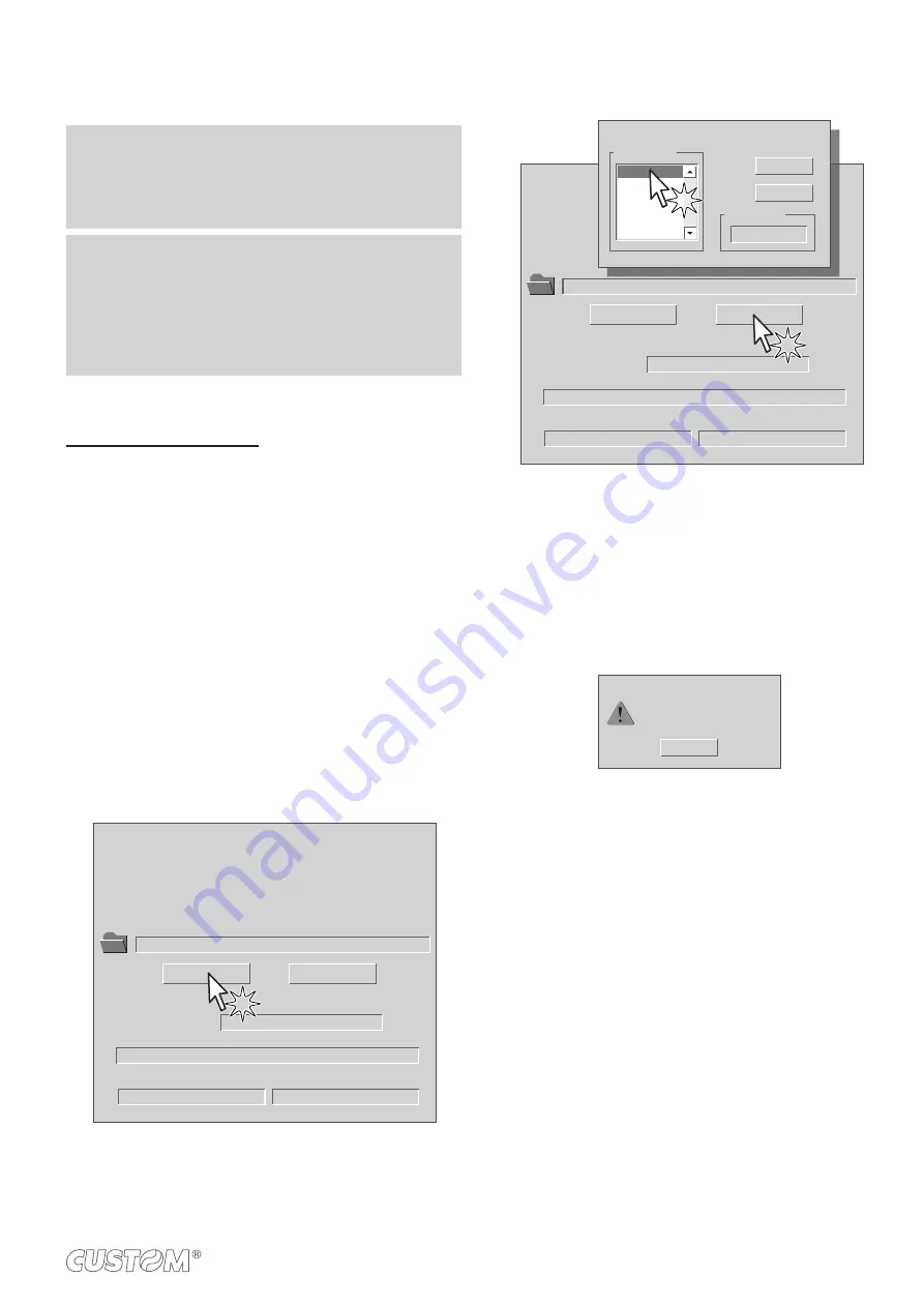
7.  Launch the software UPGCEPRN.
8.  Select the up

date ile .PSW location:

Data flush status...

Upgrade status:

No upgrade thread active...

Port config:

Communication port not init

Firmware rel.:

Hardware rel.:

PSW Version :

File [*.cfg] :

Printer type:

Select port:

None

None

None

None

None

None

File (*.psw):

Select (*.psw):

Begin upgrade

9.  Select the serial communication port (ex. COM1):

Data flush status...

Upgrade status:

No upgrade thread active...

Port config:

Communication port not init

Firmware rel.:

Hardware rel.:

PSW Version :

File [*.cfg] :

Printer type:

Select port:

None

None

None

None

None

None

File (*.psw):

C:\

<device>

.PSW

Select (*.psw):

Begin upgrade

COM1

COM2
COM3
COM4
COM5
COM6

Select the system communication port

Available port

Selected port

COM1

OK

Cancel

10.  Detecting and setting of the parameters necessary for 

serial communication are performed automatically and 
then updating begins.

11.  After a few minutes a message on the screen warns 

that the update is completed.

Upgrade OK

OK

Upgrade succesfully completed.

12. 

Print a new SETUP report to verify the new irmware 

release (see chapter 5).

55

Summary of Contents for 915DW011000300

Page 1: ...USER MANUAL VKP80II SX...

Page 2: ......

Page 3: ...is an easily acces sible outlet with a capacity of no less than 10A closely to where the device is to be installed Periodically perform scheduled mainte nance on the device to avoid dirt build up that...

Page 4: ......

Page 5: ...MANUAL For details on the commands refer to the manual with code 77200000001600...

Page 6: ......

Page 7: ...ssages 17 3 INSTALLATION 3 1 Fastening 19 3 2 Collections 21 3 3 Pinout 22 3 4 Driver and SDK 24 3 5 Paper reduction guides kit optional 25 4 OPERATION 4 1 Adjusting paper width 27 4 2 Switch the devi...

Page 8: ...supply dimensions cod 963GE020000003 optional 64 7 6 Paper speciication 65 7 7 Character sets 66 8 CONSUMABLES 9 ACCESSORIES 9 1 Adapter cable for power supply 72 9 2 Paper roll holder 73 9 3 Shutter...

Page 9: ...ion for the device and its accessories 8 CONSUMABLES description and installation of the available consumables for the device 9 ACCESSORIES description and installation of the available accessories fo...

Page 10: ...10...

Page 11: ...the components illustrated below are present and that there are no signs of damage If there are contact Customer Service 1 Documentation Short guide installation instruction sheet 2 Power supply cabl...

Page 12: ...ing lever 2 Cutter 3 Paper output 4 Status LED 5 LF LINE FEED key 6 FF FORM FEED key 7 Right cursor for paper input 8 Paper input 9 Left cursor for paper input 10 Power supply port 11 USB port 12 RS23...

Page 13: ...2 3 Device components internal views 1 Printing head 2 Paper out presence sensor 3 Roller ejector 4 Sensor for paper in presence 5 Sensor for black mark 6 Cutter 2 1 4 5 6 3 13...

Page 14: ...2 4 Product label PC Product code 14 digits SN Serial number HW Hardware release PC XXXXXXXXXXXXXX Rx HW 0000000000000000000 SN 14...

Page 15: ...FF LF FF LF FF LF FF LF FF LF FF print the SETUP report next parameter modify selected parameter POWER UP Fast push Fast push Hold down Hold down print the FONT TEST enter the SETUP MODE Fast push ski...

Page 16: ...2 6 Key functions standby LF FF LF FF Advance the paper preset length STANDBY Fast push Fast push Advance the paper manual insertion 16...

Page 17: ...GREEN ON DEVICE ON NO ERROR GREEN COMMUNICATION STATUS x 1 RECEIVE DATA x 2 RECEPTION ERROR PARITY FRAME ERROR OVERRUN ERROR x 3 COMMAND NOT RECOGNIZED x 4 COMMAND RECEPTION TIME OUT YELLOW RECOVERAB...

Page 18: ...18...

Page 19: ...OINT BOTTOM It s very important to consider the screws length not to damage the internal components placed near the ixing holes see following igure max 8 SP Decive chassis Fixing panel Fixing screw Se...

Page 20: ...Additionally the panel must provide an opening for loop of paper that meets the following measures in millimetres min 89 50 19 5 min 36 50 85 5 20...

Page 21: ...upply PC USB device PC serial device Standard USB cable Standard serial cable Power supply cable supplied ATTENTION In some using conditions we recommend the installation of a ferrite core on the powe...

Page 22: ...TE Power supply cable The following igure shows the connector pinout of the power supply cable for device Female Molex connector series 5557 n 39 01 3022 GND Black 2 Signal Cable color PIN 24V Red 1 2...

Page 23: ...the RS232 standard logic value 0 corresponds to a voltage level of between 3 Vdc and 15 Vdc and logic value 1 corresponds to a voltage level of between 3 Vdc and 15 Vdc DEVICE PC connection Use an RS...

Page 24: ...instruction get back on the README TXT ile You can ind it in the software package downloaded in advance Windows Linux Driver for JavaPOS Extract the zipped folder to the destination path desired Andro...

Page 25: ...m The kit includes the reductions for both the left paper guide and the right paper guide With both the guides assembled do not go below 45mm wide paper below this value the sensor the sensor can not...

Page 26: ...26...

Page 27: ...t Dx and Left Sx slides located at the paper infeed opening Move the right and left slides to adjust the paper width see following igure Below the right slide there are four point of reference for pap...

Page 28: ...ble to an external power supply unit Connect the power supply cable to the device Use the type of electrical power supplyindicated on the label The green status LED turn on and the devicev is ready Co...

Page 29: ...4 3 Opening cover 1 Push the release lever in the direction shown in the figure Open the device cover 2 29...

Page 30: ...o change the paper proceed as follows 1 Adjust the paper width see previous paragraphs Insert the paper into the input mouth so that it unrolls correctly Be sure that the paper is correctly positioned...

Page 31: ...of the paper roll related to the printer for a correct paper loading without a paper roll holder support The direction of the paper will always form a maximum angle of 90 or 90 with the insertion pla...

Page 32: ...d to correctly set the operation mode of the ejector with the command 0x1D 0x65 see Commands Manual and the setup parameter Automatic Ejecting see chapter 5 of this manual PRESENT EJECT model The devi...

Page 33: ...The ticket advances ahead to the ejector and is caught between the ejector rollers The printed part of ticket is collected into the ejection canal while the device continues printing Cutter Ejector ro...

Page 34: ...The ticket is waiting on the paper mouth for a preset period of time The device presents a portion of the ticket printed on the paper mouth 5 4 Paper output Ejector rollers Ticket presented 34...

Page 35: ...The device directly ejects the ticket 6 Paper output Ejector rollers Ticket ejector 35...

Page 36: ...setup parameter Paper Retracting see chapter 5 of this manual The device starts the ticket printing Printing head Paper input 1 1 For the minimum and maximum length of the ticket refer to Paper speci...

Page 37: ...The ticket advances ahead to the ejector and is caught between the ejector rollers The printed part of ticket is collected into the ejection canal while the device continues printing Cutter Ejector ro...

Page 38: ...The ticket is waiting on the paper mouth for a preset period of time The device presents a portion of the ticket printed on the paper mouth 5 4 Paper output Ejector rollers Ticket presented 38...

Page 39: ...The device retracts and collects the ticket from the mouth paper 6 Ejector rollers Ticket withdrew Ejector duct 39...

Page 40: ...40...

Page 41: ...erating parameters of the device proceed as follows STATUS LINE FEED FORM FEED RS232 Vin LF FF LINE FEED KEY hold down POWER SUPPLY PRINTER SETUP 1 2 During power up hold down the LINE FEED key while...

Page 42: ...FORM FEED RS232 Vin LF FF FORM FEED KEY fast push PRINTER SETUP 3 Proceed with the configuration by using the keys according the functions printed on paper Press the FORM FEED key to enter the configu...

Page 43: ...NTER 0 FPD 0 POWER ON COUNTER 12 PRINTING HEAD TYPE T80 RS232 Baud Rate 19200 bps RS232 Data Length 8 bits chr RS232 Parity None RS232 Handshaking Xon Xoff Busy Condition RcFull USB Address Number 0 A...

Page 44: ...MIC RAM TEST OK appears if functioning and NOT OK if faulty EEPROM TEST OK appears if functioning and NOT OK if faulty CUTTER TEST OK appears if functioning and NOT OK if faulty HEAD VOLTAGE voltage o...

Page 45: ...TS RTS BUSY CONDITION Activation mode for Busy signal RXFull D Busy signal is activated when the buffer is full OffLine RXFull Busy signal is activated when the printer is both in OffLine status and t...

Page 46: ...ct function disabled Enabled retract function enabled NOTE During power up if paper is present on the ejector and if this parameter is set to Enabled the printer will retract the paper Otherwise if th...

Page 47: ...rs for the Notch Distance are not printed In Setup mode it is possible to set the black mark distance using a values range from 0mm to 39mm The maximum distance accepted is 32mm so even if values from...

Page 48: ...e digit for tens 0 D 2 4 6 8 1 3 5 7 9 CODE TABLE num x 1 Setting the digit for units 0 D 2 4 6 8 1 3 5 7 9 NOTE See the paragraph 7 7 to learn about the character tables corresponding to the identiic...

Page 49: ...until a key is pressed or characters are received through the communication port Hexadeci mal Dump mode For each character sent the ticket shows the hexadecimal value and the ASCII codes if the charac...

Page 50: ...50...

Page 51: ...opyl alcohol Rollers Use isopropyl alcohol EVERY 5 PAPER CHANGES Cutter Use compressed air Cutter compartment Use compressed air or tweezers Paper path Use compressed air or tweezers Sensors Use compr...

Page 52: ...le and open the device cover see par 4 3 2 Remove any scraps of paper and the accumulated paper dust on the paper mouths on the printing roller on the cutter and on the area around the sensors ATTENTI...

Page 53: ...nts or hard brushes Do not let water or other liquids get inside the machine ON Rollers 1 Disconnect the power supply cable and open the frontal cover of the device see par 4 3 2 Clean the dragging ro...

Page 54: ...rd brushes Do not let water or other liquids get inside the device ON Alcohol solvent Cutter 1 Disconnect the power supply cable and open the device cover see par 4 3 2 Clean the cutter by using compr...

Page 55: ...tch ON the device 7 Launch the software UPGCEPRN 8 Select the update ile PSW location Data flush status Upgrade status No upgrade thread active Port config Communication port not init Firmware rel Har...

Page 56: ...ata flush status Upgrade status No upgrade thread active Port config Communication port not init Firmware rel Hardware rel PSW Version File cfg Printer type Select port None None None None None None F...

Page 57: ...s 8 1 32 64bit Opos Linux JavaPOS Android iOS INTERFACES RS232 serial connector from 1200 to 115200 bps USB connector SB 12 Mbit sec MEMORIES Flash memory 384 Kbytes Receive buffer 16 Kbytes Graphic m...

Page 58: ...KF50 KP460 and KP390 MITSUBISHI PF5075 TL4000 and TF1067 External roll diameter 3 max 180mm 4 upper ixing max 150mm 5 rear or lower ixing max 180mm 5 Internal roll core diameter 25mm Core type Cardboa...

Page 59: ...ser continuous mode with command 0x1D 0x65 see Command Reference 3 It is recommended to use an external shock absorber for rolls with a diameter higher than or equal to 100mm 4 Referred to model witho...

Page 60: ...oretical values 7 3 Ejector speciications Retracting function Ticket length Ticket presentation from 70mm to 80mm 10mm from 80mm to 220mm from10mm to 30mm 1 Ejecting function Ticket length Ticket pres...

Page 61: ...h 149 5mm Height 121 2mm Width 123 5mm Weight 1600 g NOTE Dimensions refers to the device without paper roll All the dimensions shown in following igures are in millimetres 83 maximum usefu 95 110 123...

Page 62: ...er positions 292 1mm Rear positions 189 4mm Lower positions 313 2mm Width 123 5mm Weight 1874g NOTES Above dimensions refer to devices without paper roll All the dimensions shown in following igures a...

Page 63: ...Height 121 2mm Width 123 5mm Weight 1600 g NOTES Dimensions refer to devices without paper roll All the dimensions shown in following igures are in millimetres 83 max utile 95 110 123 5 114 5 125 5 45...

Page 64: ...supply dimensions cod 963GE020000003 optional Length 127mm Height 35 5mm Width 56mm NOTE All the dimensions shown in following igures are in millimetres 35 5 24V GND N C 1 2 3 AC INLET 56 127 DC OUTPU...

Page 65: ...For more information about the use of paper with black mark see chapter 10 26 0 5 0 5 5 1 0 min 70 max 220 min 9 1 0 PAPER WIDTH from 60 to 82 5 NON THERMAL SIDE For lengths over 220mm be sure to leav...

Page 66: ...of coding tables that can be installed on the device CodeTable Coding table 0 PC437 U S A Standard Europe 1 Katakana 2 PC850 Multilingual 3 PC860 Portuguese 4 PC863 Canadian French 5 PC865 Nordic 11 P...

Page 67: ...859 15 Latin 9 on request 41 PC1098 Farci on request 42 PC1118 Lithuanian on request 43 PC1119 Lithuanian on request 44 PC1125 Ukranian on request 45 WPC1250 Latin 2 46 WPC1251 Cyrillic 47 WPC1253 Gre...

Page 68: ...68...

Page 69: ...of available consumables for device DESCRIPTION CODE THERMAL PAPER ROLL WITH BACK SIDE PRE PRINTED weight 58g m2 width 80mm external 48mm core 25mm 67300000000395 THERMAL PAPER ROLL weight 58g m2 widt...

Page 70: ...70...

Page 71: ...or technical speciications see the paragraph 7 1 963GE020000003 ADAPTER CABLE FOR POWER SUPPLY see the paragraph 9 1 26900000000005 PAPER ROLL HOLDER WITH NEAR PAPER END SENSOR to assemble on the righ...

Page 72: ...is available an adapter cable cod 26900000000005 supplied as an accessory for connecting the device to the external power supply unit cod 963GE020000003 optional Assembly instructions Connect the ada...

Page 73: ...h rolls of paper max 150 mm The paper roll holder can be only assembled on the right side of the device as shown in the following igures The kit includes see igure 1 Instruction sheet 2 Tie for roll b...

Page 74: ...utter device cod 976DX010000001 is available for the machine This device prevents the insertion of paper or foreign objects into the outlet of the paper The kit includes see igure 1 Instruction sheet...

Page 75: ...his kind of sensor emits a band of light and detects the quantity of light relected to it The presence of the black mark is therefore detected by the amount of light that returns to the sensor con sid...

Page 76: ...lignment you must enable the parameter Notch Alignment during the Setup procedure see chapter 5 SENSOR USED see following igures VALUE OF THE NOTCH ALIGNAMENT PARAMETER USING MODE OF SENSOR BLACK MARK...

Page 77: ...Paper with black mark In standard model the detection of black mark is performed on the non thermal side of paper by the ixed sensor BACK MARK direction of paper feed NON THERMAL SIDE 77...

Page 78: ...f the procedure result the device offers the execution of the function of paper characterization Character ize Paper and the change of the Notch Threshold parameter which represents the detection thre...

Page 79: ...bout halfway between the peak value and the maximum value of the noise THERMAL SIDE NON THERMAL SIDE Peak Notch B Mark Threshold Noise If the maximum value of noise read by the sensor is very close to...

Page 80: ...tance between the black mark edge and the alignment point is deined as Notch Distance Notch Distance value varies from 0mm minimum and 32mm maximum If the Notch Distance value is set to 0 the alignmen...

Page 81: ...To deine the alignment point you need to set the device parameters that compose the numerical value of the Notch Dis tance parameter For example to set a black mark distance of 15mm between the black...

Page 82: ...H PRINTED AREA PRINTING DIRECTION Non printable area generated from Distance between cutter printing head Value for the paper recovery after a cut where Distance between printhead and cutter 11 9mm ix...

Page 83: ...ST OK CUTTER TEST OK HEAD VOLTAGE 24 01 HEAD TEMPERATURE 24 VKP80 II SX SCODE code rel 1 00 FCODE code rel 1 00 1 Write down the data printed on the product label see par 2 4 Print a Setup report see...

Page 84: ...m biz CUSTOM S p A World Headquarters Via Berettine 2 B 43010 Fontevivo Parma ITALY Tel 39 0521 680111 Fax 39 0521 610701 info custom biz www custom biz All rights reserved Part Number 76200000005800...

Reviews: