background image

CAUTION:  Read  All  Instructions  Before  Operating  Equipment

308  Industrial  Park  Road

  Starkville,  MS  39759   USA

Tel:  662-323-9538  Fax:  662-323-6551

VERSION  1A

LFA-220M10EL

10 Element Loop Feed Beam

For 220 Mhz

INSTRUCTION MANUAL

Cushcraft

Amateur Radio Antennas

Cushcraft

Amateur Radio Antennas

Summary of Contents for LFA-220M10EL

Page 1: ...ting Equipment 308 Industrial Park Road Starkville MS 39759 USA Tel 662 323 9538 Fax 662 323 6551 VERSION 1A LFA 220M10EL 10 Element Loop Feed Beam For 220 Mhz INSTRUCTION MANUAL Cushcraft Amateur Radio Antennas Cushcraft Amateur Radio Antennas ...

Page 2: ...D OBSTRUCTIONS FAILURE TO EXERCISE THIS CARE COULD RESULT IN SERIOUS OR FATAL INJURY 2 The LFA Loop Fed Array Low Noise Yagi is very different from the traditional dipole fed Yagi in many ways with its primary benefit being unwanted noise rejection The LFA has a rectangular shaped full wave loop driven element that is laid flat on the boom between and in line with the parasitic elements Then there...

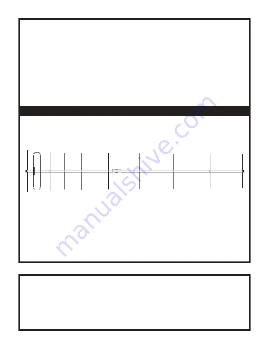
Page 3: ...ghten the bolts See next Page Install the U bolts using the 5 16 nuts 555747 385142 1 385144 1 1 4 20 nut 1 4 washer and the 5 16 split washers 564792 5 16 nut 5 16 washer U bolt 1 4 20 x 3 4 BOOM Front of antenna R1 R2 R3 R4 R5 R6 R7 R8 R9 You may place the boom on a temporary mast or support it from each end This will make assembly and measurements easier Find a location that is suitable for an ...

Page 4: ...he antenna using the 8 32 x 2 inch bolt Attach the two short 7 16 tubes to the insulator using the 8 32 x 1 inch bolt thru the holes in the ends of the tubes Go ahead and tighten the nuts but do not crush the tubes Mount the long 7 16 tube to the third hole from the rear of the boom using a longer 8 32 x 2 1 4 bolt half washer and element saddle 8 32 x 2 1 4 half washer element saddle 8 32 x 2 8 3...

Page 5: ...clamp over each end of each tube Insert the loop ends into the 7 16 tubes Don t force them Keep them straight as they go in Leave them loose for tunning the SWR later The tubes will have enough friction to stay without the hose clamps being tightened 4 Hose Clamp Rear Boom Section ...

Page 6: ...rector A chart is provided and the element colors are listed for each element Install them on the boom in the proper location using the half washer saddle and 8 32 x 2 inch bolts nuts and lock washers 3 16 ELEMENT ROD LENGTHS R1 26 1 8 INCH BROWN R2 24 3 4 INCH RED R3 22 13 16 INCH ORANGE R4 23 INCH YELLOW R5 22 13 16 INCH GREEN R6 22 7 16 INCH BLUE R7 21 7 8 INCH VIOLET R8 21 3 16 INCH GREY R9 21...

Page 7: ...a choke balun into the coax using a household cleaner or spray paint can Put 3 turns around the can and secure the coax together using cable ties Attach the balun to the boom with tape and route the coax along the boom to the mast and go down from there Once you have all the elements on in the correct location check the alignment of the elements on the boom sections Place the Boom caps on the ends...

Page 8: ...centered where you want it tighten the clamps on the tubes Do not use a wrench or powered device to tighten the clamps A nut driver or screwdriver is plenty to do the job Move out to shift frequency down The antenna is now ready for mounting on your pole or tower Route the coax along the boom and mast Secure it using cable ties or electrical tape Check the antenna over one last time to make sure e...

Page 9: ......

Page 10: ......

Page 11: ...Notes ...

Page 12: ......

Reviews: