background image

- 3 -

SETTING THE WC-603-101 BREW TIMER

Adjustment of the timer is made on a calibrated dial with a range from 0 to 100. 

This is a range of 2 to 20 minutes. The front control panel has a brew selector 

switch marked 

1

 and 

2

.

To change the setting, flip the brew selector switch to 

2

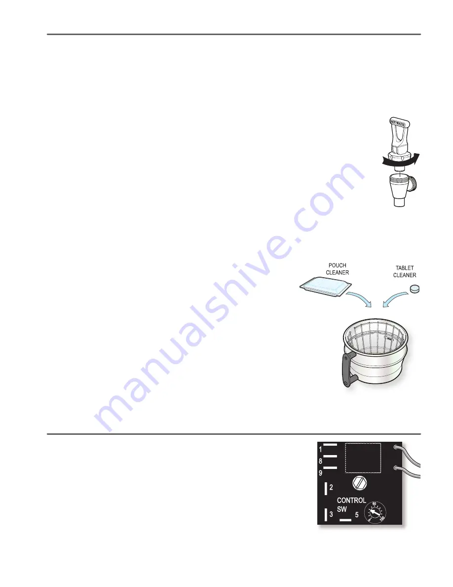
. Locate the brew timer, in-

side the top cover. Rotate timer arrow to the right to increase the brew time, rotate 

to the left to decrease the brewing time. The indicator dial is normally set pointing 

at 25. This setting is intended to deliver one gallon of water (brew 24 cups) per 

brew cycle..

Cleaning the Satellite Server

1.  Empty any remaining coffee from the Satellite server. 

2.   Fill the liner with a mild detergent solution and let it stand for 10 to 15 minutes. 
3.   After about 15 minutes take a sponge brush and scrub out the stainless steel liner. 

4.   Drain out the detergent solution from the server. Rinse in a sink with running water.

5.  Repeat this rinsing until the water runs clear.

CLEANING THE FAUCET

1.  Remove the faucet handle assembly. Take hold of the bonnet and turn counterclockwise to unscrew it from the faucet. 

2.   Clean the handle assembly with a mild detergent solution. When clean, rinse the handle with water. Inspect for cracks 

or tears in the seat cup. Replace if the seat cup damaged.

3. Clean the coffee level gauge glass.

a.  Remove the gauge glass cap unscrewing it from the top of the shield.

b.  Carefully, pull out the gauge glass. Brush out the inside of the glass with a detergent solution. Rinse the sight glass 

tube of all detergent residue.

c.  Inspect the gasket seals at the top and bottom of the gauge glass. Clean these gaskets.
d.  Assemble the gauge glass. Make sure gaskets are properly seated.
e.  Hand tighten the gauge glass cap.

Pouch Cleaner

You may use a pouch or tablet cleaner to easily clean both the brew cone and the coffee vessel.
1.  Place a pouch or tablet cleaner into the brew cone. Place an empty server on the brew 

deck.

2.  Press the brew button to run a full brew cycle into the server. You will see that the 

cleaner pouring from the brew cone is blue.

3.  At the end of the brew cycle, discard the used filter cleaner pouch. The tablets should have disolved in 

the brew cycle.

4.  Allow the cleaner to soak in the coffee server for a few minutes.
5.  Dump out the cleaner from the coffee server into a sink. You can simply open the faucet and let the 

blue cleaning solution to flow out.

6.   Return the empty coffee server to the brew deck. Install the brew cone onto the brewer. Run another 

brew cycle of hot water to rinse the brew cone and into the server. 

7.  Empty the rinse water from the coffee server. Repeat the rinse cycle before putting the coffee server 

back into service.

Summary of Contents for GEM-120A

Page 1: ...ur Curtis Company Service Technician DO NOT immerse the unit in water or any other liquid To reduce the risk of fire or electric shock DO NOT open service panels There are no user serviceable parts inside Keep hands and other items away from hot areas of the unit during operation Never clean with scouring powders or harsh chemicals INSTALLATION This Curtis unit is pre set and ready to go from the ...

Page 2: ...s prepare a mild solution of detergent and warm water CAUTION Do not use cleansers bleach liquids powders or any other substance containing chlorine These products promote corrosion and will pit the stainless steel USE OF THESE PRODUCTS WILL VOID THE WARRANTY DAILY CLEANING 1 Wipe exterior surfaces with a damp cloth removing spills and debris 2 Slide the brewcone out and clean it Wipe the sprayhea...

Page 3: ...t cup Replace if the seat cup damaged 3 Clean the coffee level gauge glass a Remove the gauge glass cap unscrewing it from the top of the shield b Carefully pull out the gauge glass Brush out the inside of the glass with a detergent solution Rinse the sight glass tube of all detergent residue c Inspect the gasket seals at the top and bottom of the gauge glass Clean these gaskets d Assemble the gau...

Page 4: ...ned out 3 Grounded probe 4 Defective or burned out water level control board PROBLEM WATER IN TANK DOES NOT GET HOT OR WATER TEMPERATURE TOO LOW POSSIBLE CAUSE SOLUTION 8 Thermostat is off Check the thermostat to make sure it is in the ON position Turn the thermostat stem clockwise until it stops 9 Burned out heating element Check element for continuity and or check with clamp ammeter This should ...

Page 5: ...d 110 to 120 volts across terminals 8 and 9 of the timer The RED wire on terminal 8 supplies power to open the dump valve If no voltage is present replace the timer If the timer works when the brew switch is pressed then check the dump valve using a voltmeter on the terminals If it shows 110 to 120 volts but no water flows through the valve clean out the valve or replace the coil 11 Water level is...

Page 6: ... 6 GEMINI 120A Parts List 8 27 28 B 25 6 3 16 14 21 1 4 20 24 5 7 13 9 10 11 12 2 15 15 18 17 23 26 29 30 31 19 21 22 ...

Page 7: ...SY 100W 120V WITH SILICONE BOOTS SWITCH TOGGLE SPST 25A 125 250 VAC RESISTIVE LEG SCREW BUMPER 3 8 16 STD BREW CONE ASSY W SPLASH POCKET NON METAL DELUXE OPTIONAL COVER FRONT GEM 120A 120P 230A 200R 300IL 600ILD COVER TOP ALPGT D500GT D60GT TLP TCTS CBS GEMSS PLUG TANK DRAIN ULTEM 1000F KIT VALVE REPAIR USE ON WC 826 WC 826L WC 847 WASHER 35 GPM 5 USE ON WC 825 LID ASSEMBLY TANK TANK COMPLETE GEM ...

Page 8: ...ORD 6 18 3 BLK SWITCH ROCKER 120V RED SATELLITE SERVER 1 GAL LID SATELLITE PLASTIC GEM3 GAUGE GLASS ASSEMBLY 8 C SHIELD 8 INCH GAUGE GLASS GAUGE GLASS 8 INCH BRACKET GAUGE GLASS FORMED SHANK FAUCET D T CHROME FAUCET S NONLOCKING FAUCET ESP BLACK NONLOCKING OPTIONAL KIT FAUCET S SERIES SATELLITE STAND LEG SCREW BUMPER 3 8 16 STD KIT WARMER ELEMENT 100W 120VAC ILLUSTRATED PARTS LIST GEM 3 5 8 11 13 ...

Page 9: ... 9 ELECTRICAL DIAGRAM GEM120A 10 ...

Page 10: ... 10 ELECTRICAL DIAGRAM GEM120A 63 ...

Page 11: ... 11 ELECTRICAL DIAGRAM GEM 5 8 ROUGH IN DRAWING GEM 120A ROUGH IN DRAWING GEM 3 GEM 5 ...

Page 12: ...es 3 Improper voltage Equipment must be installed at the voltage stated on the serial plate supplied with this equipment 4 Improper water supply This includes but is not limited to excessive or low water pressure and inadequate or fluctuating water flow rate 5 Adjustments and cleaning The resetting of safety thermostats and circuit breakers programming and temperature adjustments are the responsib...

Reviews: