


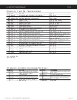


Connect the Water Supply
5 Flush the water supply line prior to installation to
QVSHFBJSBOEEFCSJTGSPNUIFXBUFSmMUFSBOEUVCJOH
6
$POOFDUUIFXBUFSTVQQMZMJOFUPUIFnBSFmUUJOHPOUIF
back of the urn control panel. Leave the water supply
valve closed until power is connected.
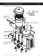
Connect the Wiring
Remove the electrical access cover on the left side of
the urn.
Loosen the strain relief under the electrical access
hole and feed the power cable into the chassis.
9 Connect the wires on the power cable to the terminal
block inside the unit. Use the proper wire gauge, plus
25%. Refer to the
SPECIFICATIONS
for the required
urn wire gauge.
10 Connect the ground wire to the chassis grounding
screw inside the unit.
11 Tighten the strain relief.
12 Replace the access cover.
13 Connect the power cable wires to the terminals in the
junction box. See the
ELECTRICAL SCHEMATIC
for
the power supply requirements.
14 Some models are equipped with a second 120 Volt
power cord. Connect it to a dedicated electrical outlet
protected by a 15-20 Amp. circuit breaker.
continued...
INSTALLATION INSTRUCTIONS
II7
36"650."5*$*/45"--"5*0/*/4536$5*0/4ø
/$
WARNING:
Turn off power to the junction box at
the circuit breaker panel before connecting the
power cable to the urn.
WARNING:
The body of the urn must be
securely grounded with a separate grounding
conductor and never with the neutral conductor
of a single phase, 3 wire system.
Left side
of urn
Strain
relief
Grounding
screw
Back of
urn