Current Designs 932 fORP Getting Started Download Page 3

Setting Up the 932 fORP

Setting up the 932 is a matter of making connections and choosing the output you want.

The 932 supports many different handheld devices, and can produce many different types of outputs.

In the following sections we'll cover how to make these connections, and how to choose the mode you want.

Making the Connections

These things need to be connected:

the handheld devices - Plug the handheld device either directly into the 932, or connect it through a removable
bundle.
the power supply
the output cable (USB, serial, parallel, or other) to the host computer.

You may also want to connect an optical or TTL trigger.

These connections are all made to ports on the 932 rear panel, which is described in more detail under 

932RearPanel

.

Choos ing the Us e Mode

Each output behavior is a "Use Mode". A brief descriptive list of the available modes is given in 932 Use Modes

?

.

Most users will only be interested in one or two of these modes.

The choice of use mode is determined by:

Cabling to the host

1.

Type of connected handheld device

2.

Desired output format

3.

Your choices are made using the knob on the front panel, guided by the display.
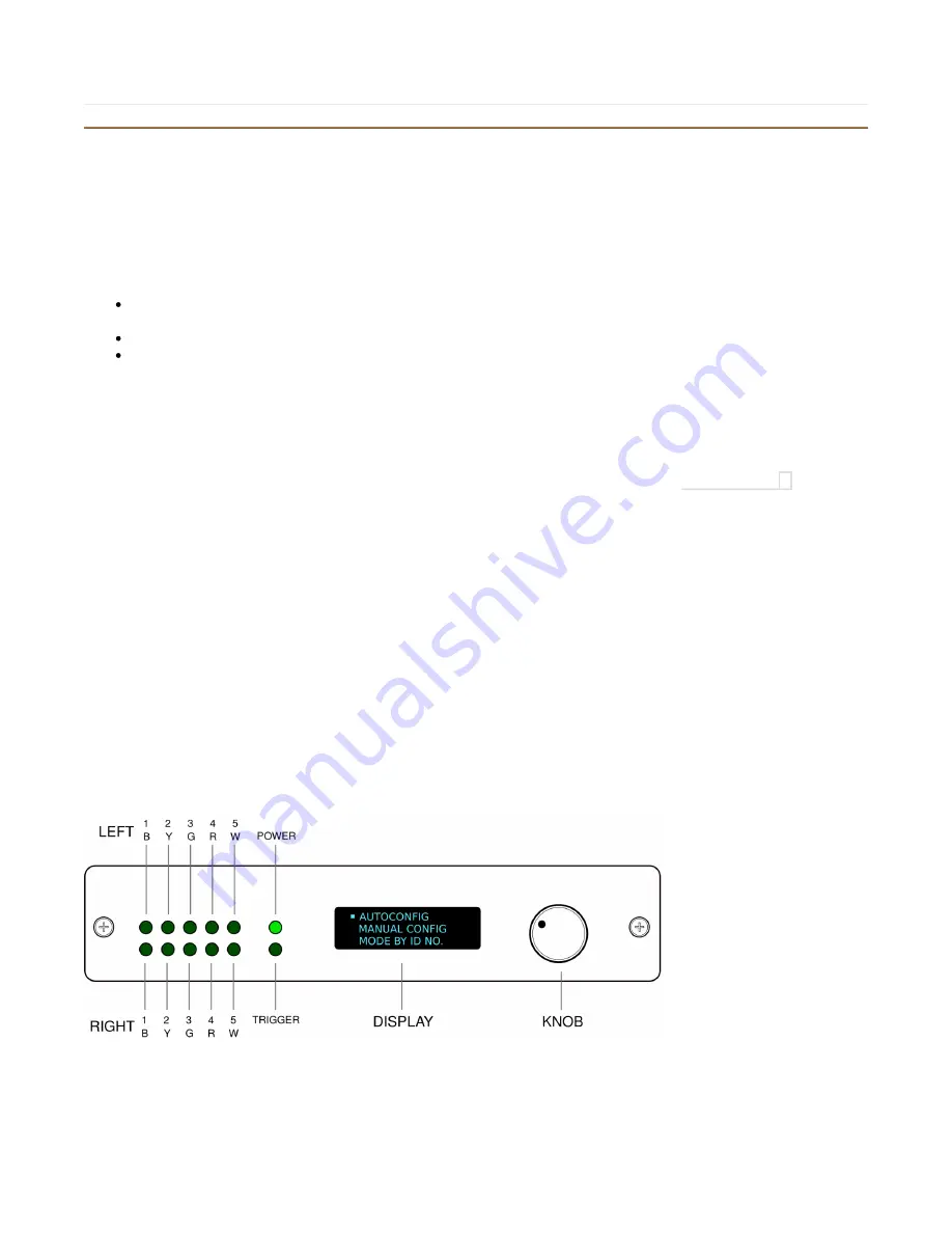
932 Front Panel

The 932 front panel uses a shaft encoder and display to let the user choose among many operating modes, and also displays
real-time activity using a bank of 10 green LED indicators.

The shaft encoder works together with the display to allow choices from menus, using clockwise and counter-clockwise
rotations and a push-click for selections.

Front Panel Indicator Functions  - Button Box Modes

This drawing shows the front panel of the 932 with the indicator LEDs labeled as they would function in typical button box
modes.

In some modes the indicator LEDs are used to indicate motion (for the scroll wheel device, for instance) or activity (scanning

Summary of Contents for 932 fORP

Page 1: ...Getting Started The 932 fORP ...

Page 2: ......

Page 3: ...e A brief descriptive list of the available modes is given in 932 Use Modes Most users will only be interested in one or two of these modes The choice of use mode is determined by Cabling to the host 1 Type of connected handheld device 2 Desired output format 3 Your choices are made using the knob on the front panel guided by the display 932 Front Panel The 932 front panel uses a shaft encoder and...

Page 4: ...s the interface will attempt to identify it and to set the gain properly on its channels Because the gain is automatically determined at this time the system should work reliably both with and without removable bundles connected Also if a cable usually a serial cable or a USB cable is connected to a host computer the interface will identify that cable and limit the available mode choices to ones w...

Page 5: ...using the number the hardware interface and output format are set at one time and no questions are asked Switching Handheld Devices When you switch from one type of handheld device to another the 932 needs to be told of this change For instance when you unplug a button box and connect a scroll wheel device in its place you should push the knob and and answer YES to CHANGE MODES What Happens at Pow...

Page 6: ...s model number 3M 10136 3000PE P3 USB outputs For most users this is the main data output port It is connected to the host computer using a commonly available USB cable 5 pin mini USB to USB P4 Main Optical trigger input This port accepts optical trigger signals such as those produced on some Siemens MR scanners It uses an Agilent HFBR connector P5 Main Optical Port This port connects to a Current...

Page 7: ... box emulation Trackball Modes Mode Identifier USB Serial Description Notes 500 HID MOUSE 1 HID mouse with two buttons 503 HID COMPOSITE HID mouse with two buttons keyboard for trigger 550 SERMOUSE Legacy serial mouse emulation 590 TRACKBALL CAL na na Trackball gain calibration mode Joystick Modes Mode Identifier USB Serial Description Notes 600 HID MOUSE 1 HID mouse with two buttons 601 HID JOYST...

Page 8: ...antly but in that case in may also make sense to be sure that the ball has not gotten dirty or abraded over time How to Calibrate Begin with the optical components connected in the way that you intend to use them If possible have the trackball close enough to the 932 interface that the LEDs on the 932 are visible Select mode 590 using the knob and the MODE BY ID NO choice the left most LEDs should...

Page 9: ... com CdiDocs WebHome If you don t find good help on this site please contact us by email support curdes com or phone 215 387 5456 For users who want to flash their devices with new firmware Please login to the site and follow this link http www curdes com CdiDocs UpdatingFirmwarePython html ...

Page 10: ...dicators respond correctly 1 4 Is the correct handheld device indicated on the display The model number which appears on the label on the handheld device should match what is on the middle line of the display For instance if you using a HHSC Main 1x4 D button box the middle line of the display should read HHSC Main 1x4 D In some cases the system will work properly even though the display indicates...

Page 11: ... losses that are too high for the fixed gain of the 932 In this case you can try selecting LEGACY HANDHELD instead Now the 932 will use stored gain values for each channel button so it can compensate for a wide range of optical losses on a channel by channel basis You ll need to calibrate the system for the handheld you intend to use This is done using the LEGACY HH CAL mode described below At the...

Page 12: ...way things worked with the earlier HH series of handheld devices This change was made to facilitate automatic recognition and automatic gain compensation of the button boxes The HH button boxes are still available and we will continue to repair them indefinitely Old trackballs joysticks and custom devices Most of these devices are almost completely compatible with the 932 and can be made to be com...

Reviews: