background image

M48 Tank

6

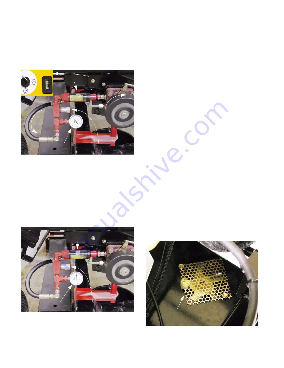
4.23. When the fluid is between 160-210 deg. f.                

(71-90 deg. c.) apply full forward drive pressure 
to the lap bar with the engine running at full 
speed (3600 RPM) while an assistant closes the 
valve to the point where pressure reaches 300 
PSI  (21 Bar.). See Figure 4.23.


NOTE: 

It may be necessary to over-shoot 300 

PSI slightly, then open the valve to reduce pres-
sure to 300 PSI.

4.24. Take note of the reading on the flow meter por-

tion of the test kit when the pressure gauge 
reads 300 PSI.

4.25. Continue closing the valve until the pressure 

reading reaches 1,100 PS I  (76 bar.).  Take note 
of the flow reading. See Figure 4.25.

4.26. Subtract the 1,100 PSI flow reading from the 300 

PSI flow reading.  The resulting figure is called 

flow droop

”.

4.27. Interpretation: flow droop greater than 1.5 GPM 

indicates a pump that is not performing as well 
as it should.

NOTE: 

A blocked filter may account for some 

loss of performance.   

4.28. Within the two year Cub Cadet Commercial war-

ranty period, replace the pump if it does not per-
form as specified and all other factors have been 
eliminated.

4.29. If a hydro pump requires repair, refer to Hydro-

Gear publication “BLN-51337” for complete ser-
vice instructions.

4.30. If the hydro pump and all other factors are O.K., 

replace the hydro motor.  

NOTE: 

The hydro motor is not serviceable.  

Replace it as a unit if it fails.

5.

REPLACING THE HYDRO PUMP

5.1.

If the cutting deck is currently on the unit, 
remove it.

5.2.

Safely lift and support the rear of the tank.

5.3.

Remove the rear wheels using a 3/4” socket.

5.4.

Tilt the seat up, and disconnect the negative bat-
tery cable.  

5.5.

Remove the screen that covers the opening over 
the cooling fans on the hydro pump to be 
removed using a 3/8” wrench. See Figure 5.5.

Figure 4.23

FLOW

       300 PSI

10 GPM

BUILD PRESSURE

CLOSE VALVE TO 

SPINNING

CONTROL 
CONSOLE INSET:
           3600 RPM

Figure 4.25

1100 PSI

9 GPM

VALVE CLOSED 
FURTHER

Figure 5.5

REMOVE DEBRIS SCREEN

Summary of Contents for THE TANK M48

Page 1: ... 00966 This Service Manual is not a substitute for the Operator s Manual You must read understand and follow all of the directions in this manual as well as the Operator s Manual before working on this power equipment 11 2003 CUB CADET LLC P O BOX 361131 CLEVELAND OH 44136 0019 Cub Cadet M48 Tank ...

Page 2: ......

Page 3: ... this Section 1 Changes for 03 and 04 1 Drive System Adjustment 1 Hydro Pump Testing 4 Hydro Pump Replacement 6 Hydro Pump Motor Replacement 10 Brake Linkage Adjustment 13 M72 Tank 16 Other Tank Features 19 Kohler EFI 23 EFI Controls 26 ...

Page 4: ......

Page 5: ...r are accessible beneath the seat See Figure 3 2 Figure 3 2 RESERVOIR OIL FILTER BATTERY 3 3 The hydraulic fluid level should be at the second hole in the filler neck of the reservoir See Figure 3 3 NOTE It is very important that the hydraulic oil does not become contaminated Clean the sur rounding area thoroughly prior to opening any part of the hydraulic system NOTE The hydraulic drive system co...

Page 6: ...or arm on the brake assembly The actuator arm should return to center releasing the brakes See Figure 3 7 3 8 Check the condition of the belt tensioner and belt that drives the hydro pumps See Figure 3 8 3 9 Before making neutral control and tracking adjustments make sure the relief valves on both hydro pumps are fully closed 3 10 To check neutral control safely lift and support the rear wheels of...

Page 7: ...ertised See Figure 3 13 NOTE Remove the control console to gain access to the return to neutral cylinder Figure 3 13 RETURN TO NEUTRAL CYLINDER RIGHT 3 14 Loosen the jam nuts at each end of the hydro control link rods and rotate the rods to lengthen or shorten them See Figure 3 14 3 15 Start the engine and release parking brake to test then turn the engine off to make the adjust ment 3 16 Tighten ...

Page 8: ...ed or removed 4 5 If the unit has been run recently allow it to cool before doing loosening any hydraulic fittings WARNING Hot hydraulic fluid can cause seri ous burns WARNING Release of pressurized hydraulic fluid can cause serious of fatal injury 4 6 Open the relief valve on the hydro pump that is to be tested This will relieve any residual hydraulic pressure 4 7 Confirm that the hydraulic press...

Page 9: ...arts during this test nor should they place themselves in any position where a loss of foot ing or balance might bring them into contact with rotating components Loose hair or garments should be secured to avoid the possibility of entanglement with rotating components Figure 4 12 4 15 Remove the stop bolt that sets the end of the travel of the lap bar that controls the hydro pump to be tested See ...

Page 10: ...TE A blocked filter may account for some loss of performance 4 28 Within the two year Cub Cadet Commercial war ranty period replace the pump if it does not per form as specified and all other factors have been eliminated 4 29 If a hydro pump requires repair refer to Hydro Gear publication BLN 51337 for complete ser vice instructions 4 30 If the hydro pump and all other factors are O K replace the ...

Page 11: ... pulley from the tapered and keyed input shaft of the hydro pump See Figure 5 10 5 11 Disconnect the rod end on the back of the hydro control rod from the control arm on the hydro pump using a 9 16 wrench and a 1 2 wrench See Figure 5 11 NOTE There is a lock washer positioned between the rod end and the control arm 5 12 Thoroughly clean the area surrounding any hydraulic fittings to be loosened or...

Page 12: ...urn line that runs from from the outboard side of the hydro pump to the res ervoir using a 7 8 wrench on the nut and an 11 16 wrench to hold the fitting on the hydro pump Plug the line cap the fitting on the pump See Figure 5 14 5 20 Disconnect the two lines that connect the hydro motor to the back of the hydro pump using a pair of 7 8 wrenches Plug the lines See Figure 5 20 5 21 Remove the two O ...

Page 13: ...wo bolts that secure it in position line up with the two mount ing ears on the pump and the input shaft slips into the pulley as the pump is raised up to the hydro pump support plate See Figure 5 30 5 31 Start both nuts that hold the pump onto their car riage bolts 5 32 As the pump is tightened into position rotate the pulley to align the keyways allowing the pulley to seat on the input shaft 5 33...

Page 14: ... the area surrounding any hydraulic fittings to be loosened or removed 6 6 If the unit has been run recently allow it to cool before doing loosening any hydraulic fittings WARNING Hot hydraulic fluid can cause seri ous burns WARNING Release of pressurized hydraulic fluid can cause serious or fatal injury 6 7 Open the relief valve on the hydro pump This will relieve any residual hydraulic pressure ...

Page 15: ...the way See Figure 6 13 6 12 Place a catch pan under the hydro motor and have two 1 2 JIC plugs within reach Figure 6 11 BRAKE LINK BRAKE ARM HAIRPIN CLIP COTTER PIN CASTLE NUT HIGH PRESSURE LINES 6 13 Disconnect the high pressure lines from the the hydro motor one at a time using a 7 8 wrench A 1 wrench may be required to hold the fittings on the hydro motor Plug the lines See Figure 6 13 6 14 Re...

Page 16: ...ke drum from the axle See Figure 6 20 6 21 Mark the orientation of the brake assembly on the hydro motor 6 22 Remove the four socket head cap screws that hold the brake assembly to the hydro motor using a 1 4 allen wrench 6 23 Transfer the four mounting bolts from the old hydro motor to the new one Replace any that show signs of wear or damage 6 24 Position the three motor spacers on the bolts and...

Page 17: ...tructions NOTE If the hydraulic system has been drained and flushed with 20W50 install a new filter and follow the instructions for refilling the hydraulic system in the Operator s and Service Manual 6 35 Install the wheels lower the TANK to the ground and test run it in a safe area Make any neck laces adjustments before installing the cutting deck Figure 6 28 7 BRAKE LINKAGE ADJUSTMENT 7 1 With t...

Page 18: ...t the rear brake arm assembly moves freely on the rear bellcrank shaft is suffi ciently well lubricated and is free from excessive play caused by worn busings See Figure 7 12 NOTE If rear brake arm assembly service is needed the rear bell crank shaft that the arms pivot on can be easily removed by unbolting the brake shaft holders removing the cotter pins and washers that locate the brake arm asse...

Page 19: ...DLE BRAKE ROD BRAKE BEARING HUB ARM BRAKE SWITCH Figure 7 15 COLLAR BRAKE BEARING HUB FRONT SHAFT BELLCRANK 7 16 Check the brake arm on the brake assembly for freedom of movement It should return to center 7 17 Reconnect the brake link rods and brake con necting rods to the rear brake arm assemblies 7 18 Apply light rearward pressure to each brake con necting rod The clevis pin at the rear end of ...

Page 20: ... action is inconsistent check for bent or misaligned rods and links 7 26 Install the rear wheels tightening the lug nuts to 50 70 ft lbs Lower the TANK to the ground 7 27 Install the floor panel 7 28 Test run the TANK in a safe area before return ing it to service Check the function of the park ing brakes NOTE A dragging parking brake will cause tracking issue and drive noise on the effected side ...

Page 21: ...8 3 8 4 The larger heavier decks have a foot assist pedal to help raise and lower the deck See Figure 8 4 Figure 8 3 Figure 8 4 8 5 Heavier hardware connects the deck to the hangers See Figure 8 5 8 6 Heavier front pivot bar and wider front track See Figure 8 6 Figure 8 5 Figure 8 6 ...

Page 22: ... brake arm assem blies have been doubled up on each side Instead of a single rear brake arm assembly per side two are used in tandem See Figure 8 8 8 9 The parking brake lever has been moved up to a more convenient location 8 10 A larger engine is required to power the larger deck and heavier total weight of the mower A 28 H P Generac Guardian engine is employed See Figure 8 10 Figure 8 7 Figure 8...

Page 23: ...t bid specifications See Figure 9 2 Figure 9 1 Figure 9 2 9 3 The TANK exhaust systems all feature a new aluminized finish This finish resists corrosion better than the heat paint that is more commonly used It also dissipates heat more effectively producing noticeable improvements on chassis dynamometers See Figure 9 3 9 4 Some features of the 72 deck have been extended throughout the TANK model r...

Page 24: ... vertical plane It can be tensioned with foot pressure and the rear wheel does not interfere with its travel See Figure 9 7 9 8 Heavy duty spherical rod ends on the arms at the front of the deck See Figure 9 8 9 9 The arms themselves are cast iron and the lift shaft is heavier See Figure 9 9 Figure 9 6 Figure 9 7 Figure 9 8 Figure 9 9 ...

Page 25: ...1 Figure 9 10 Figure 9 11 9 12 The deck support plates are larger this year to prevent plate bending and separation See Figure 9 12 9 13 The baffling airflow and strength of the deck have all received some improvements this year 9 14 The trailing edge of the discharge opening has been swept back and the bar that prevents foot penetration has been modified Both changes improve strength and airflow ...

Page 26: ...ia Gap at the leading edge also improves airflow and products the internal shape of the deck from damage if some thing is hit hard enough to bend the reinforced leading edge See Figure 9 16 9 17 The under deck baffling has been reinforced and a stealth baffle has been added between the second and third blades See Figure 9 17 Figure 9 15 Figure 9 16 Figure 9 17 ...

Page 27: ...e fuel requires a pressure drop within the throat of the carbu retor The venturi that creates this pressure drop is a partial obstruction of the path into the engine Until recently the advantage offered by fuel injection have not been worth the expense that they add to out door power equipment Fuel injection systems have become less expensive and more dependable in the past two decades At the same...

Page 28: ... engine runs out of fuel turn the key off immediately Running dry will damage the pump NOTE The fuel pump will run briefly each time the key switch is turned on This pressurizes the system If fuel pressure is absent and the fuel pump cannot be heard when the key switch is turned on the fuel pump may not be getting electricity Check for power before condemning the fuel pump NOTE The fuel pump is pr...

Page 29: ... shrader valve on the fuel rail This will check regulated fuel pressure If fuel pressure at the shrader valve is below 36 PSI isolate the fuel pump and check output pressure and volume Figure 10 8 High pressure from fuel pump Regulated pressure to rail via filter Return to tanks Vacuum barb not used for this application 10 9 The fuel filter is easily accessible See Figure 10 9 NOTE Use only identi...

Page 30: ...gh impedance tester eg Thexton model 125 Conventional testers pass the current they are checking through a small incandescent bulb In some cases the bulb draws more power than the circuit in the computer over loading the cir cuit and complicating the diagnostic process by inducing a circuit failure High impedance testers do not actually pass much current and the LED indicator will not draw enough ...

Page 31: ...spect the circuit may be tested with a commonly available noid light or the injector may be triggered using an electronic fuel injection pulse timer eg Thexton model number 139 in conjunction with a fuel pressure gauge With the key switch off triggering the injector should result in a measured drop in fuel pressure Figure 11 7 11 9 The ignition coils are also controlled by the ECU Each cylinder ha...

Page 32: ...st be performed 11 13 The engine temperature has a bearing on the fuel air mixture and ignition timing The ECU takes the engine s temperature with a ther mometer in the engine oil When the engine is cold the oil temperature is the same as the ambient temperature Being an air cooled engine as the engine warms up the oil temperature reflects a balance between engine load and ambient temperature when...

Page 33: ...ion from the previous two bullet points a bad oxygen sensor will not cause idle problems or cold running problems There is only one wire on the oxygen sensor used in this application It does not have a heat ing element in it nor does it have a ground wire Some automotive applications have both of these features Because it does not have a ground wire it grounds through the body of the sensor and ba...

Reviews: