background image

S

ection

 6 — M

aintenance

 & a

djuStMentS

29

4. 

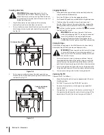
Turn on the water supply. 

5. 

From the tractor operator’s seat, start the engine and 

engage the PTO. Allow to run as needed. Disengage the 

PTO and stop the engine.

6. 

Turn off the water supply. 

7. 

Pull back the lock collar of the nozzle adapter to disconnect 

the adapter from the nozzle. 

8. 

Repeat the previous steps to clean the deck using the 

nozzle at the other end of the deck.

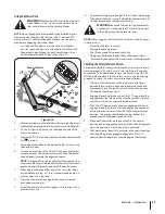
Tractor Storage

If your tractor is not going to be operated for an extended period 

of time (thirty days to approximately six months), the tractor should 

be prepared for storage. Store the tractor in a dry and protected 

location. If stored outside, cover the tractor (including the tires) to 

protect it from the elements. The procedures outlined below should 

be performed whenever the tractor is placed in storage.

1. 

Change the engine oil and filter following the instructions 

provided in the engine manual.

WARNING! 

Never store the tractor with fuel in the 

tank indoors or in poorly ventilated enclosures, where 

fuel fumes may reach an open flame, spark or pilot 

light as on a furnace, water heater, clothes dryer, etc.

2. 

If storing the tractor for 30 days or more:

a.  To prevent gum deposits from forming inside 

the engine’s carburetor and causing possible 

malfunction of the engine, the fuel system must be 

either completely emptied, or the gasoline must be 

treated with a stabilizer to prevent deterioration.

WARNING! 

Fuel left in the fuel tank deteriorates 

and will cause serious starting problems.

b.  Using a fuel stabilizer:

• 

Read the product manufacturer’s instructions 

and recommendations.

• 

Add to clean, fresh gasoline the correct 

amount of stabilizer for the capacity 

(approximately 3 gallons) of the fuel system.

• 

Fill the fuel tank with treated fuel and run the 

engine for 2-3 minutes to get stabilized fuel 

into the carburetor.

c.  Emptying the fuel system:

• 

Prior to putting the tractor in storage, monitor 

fuel consumption with the goal of running 

the fuel tank empty.

• 

Close the fuel valve. Disconnect the fuel line 

from the carburetor and put the end into an 

approved fuel container.

• 

Open the fuel valve and drain the fuel tank 

and line into the approved container. Reinstall 

the fuel line on the carburetor.

• 

Start the engine and allow it to run out of fuel. 

This will prevent gum and varnish deposits 

from forming. Replace the fuel filter.

3. 

Remove the spark plugs and pour approximately one 

ounce of oil into each cylinder. Crank the engine one or 

two turns to spread the oil evenly on the cylinder walls. 

Replace the spark plugs.

4. 

Clean the engine and the entire tractor thoroughly.

NOTE: 

Use of a pressure washer or garden hose is not 

recommended to clean your tractor. This may cause 

damage to electrical components, spindles, pulleys, 

bearings or the engine. The use of water will result in 

shortened life and reduce serviceability.

5. 

Sharpen the blades so that the mower will be ready to use 

when needed.

6. 

Protect the metal surfaces. Repair scratches with the 

appropriate touch-up spray paint. Brush a rust preventive 

oil on any unpainted surfaces including the pulleys and 

blades. (Be careful not to get any oil on the drive belts.)

7. 

Clean and fully charge the battery, then disconnect the 

negative cable at the battery to prevent possible discharge. 

Recharge the battery periodically when in storage. 

NOTE: 

Remove the battery if exposed to prolonged periods 

of sub-freezing temperatures. Store in a cool, dry location 

where temperatures are above freezing. 

8. 

Lubricate all lubrication points.

9. 

Inspect the hydraulic hoses, lines and fittings. Replace as 

necessary.

10. 

Jack the mower up and store it on blocks to take the weight 

off of the tires.

Removing The Tractor From Storage

1. 

Check the battery. Charge if necessary.

2. 

Lower tractor off blocks, and inflate the tires to the 

recommended pressure.

3. 

Remove the spark plugs and wipe them off. Using the starter, 

crank the engine to pump the excess oil out of the spark 

plug holes. Replace the spark plugs and the ignition leads.

4. 

If drained before storing, fill the fuel tank with clean, fresh 

gasoline.

5. 

Check the level of the engine oil in the crankcase and the 

hydraulic reservoir tank.

6. 

Start the engine and allow to idle for a few minutes to 

ensure engine is operating properly.

7. 

Drive the tractor without a load to make certain all the 

tractor systems are functioning properly.

Summary of Contents for Tank LZ

Page 1: ...n Practices Set Up Operation Maintenance Service Troubleshooting Warranty WARNING READ AND FOLLOW ALL SAFETY RULES AND INSTRUCTIONS IN THIS MANUAL BEFORE ATTEMPTING TO OPERATE THIS MACHINE FAILURE TO COMPLY WITH THESE INSTRUCTIONS MAY RESULT IN PERSONAL INJURY Form No 769 07370 February 23 2012 Tank LZ ...

Page 2: ...operate and maintain your machine Please be sure that you and any other persons who will operate the machine carefully follow the recommended safety practices at all times Failure to do so could result in personal injury or property damage All information in this manual is relative to the most recent product information available at the time of printing Review this manual frequently to familiarize...

Page 3: ...io 44136 0019 This spark ignition system complies with Canadian ICES 002 DANGER The engine manufacturer has supplied an engine owner s manual for information regarding US Environmental Protection Agency EPA and California Air resources Board CARB regulations relating to emission control systems maintenance and warranty Making any unauthorized alterations or modifications to the engine fuel or vent...

Page 4: ...aining this machine Long hair loose fitting clothing or jewelry may get entangled in moving parts Follow all federal state and local guidelines regarding the use of personal protective equipment 10 Be aware of the mower and attachment discharge direction and do not point it at anyone Do not operate the mower without the discharge cover or entire grass catcher in its proper place 11 Do not put hand...

Page 5: ...terrain could overturn the machine Tall grass can hide obstacles 3 Use slow speed Choose a low enough speed so that you will not have to stop while on the slope Avoid starting or stopping on a slope If the tires are unable to maintain traction disengage the blades and proceed slowly and carefully straight down the slope 4 Keep all movements on the slopes slow and gradual Do not make sudden changes...

Page 6: ... except when the ROPS are a Not properly installed and or not properly secured onto the machine b Damaged in such manner that their structural integrity has been compromised c Not in their fully upright and locked position 4 Seat belts are attached to the movable portion of the seat when suspension seats are utilized and therefore the seat mounting base must be secured to its pivot means and the p...

Page 7: ...el cap or add fuel while the engine is hot or running Allow engine to cool at least two minutes before refueling h Never over fill fuel tank Fill tank to no more than inch below bottom of filler neck to allow space for expansion i If necessary use a funnel to avoid spillage j Replace fuel cap and tighten securely k If fuel is spilled wipe off the engine and equipment Wait 5 minutes before starting...

Page 8: ...ay Tampering with the governor setting can lead to a runaway engine and cause it to operate at unsafe speeds Never tamper with factory setting of engine governor Notice Regarding Emissions This machine is equipped with an engine that is certified to federal EPA emission standards for non road engines and equipment and where applicable to California Air Resources Board CARB emission standards The e...

Page 9: ...n cause serious personal injury WARNING THROWN OBJECTS This machine may pick up and throw objects which can cause serious personal injury BYSTANDERS Keep bystanders helpers children and pets at least 75 feet from the machine while it is in operation MAX WARNING SLOPE OPERATION Do not operate this machine on a slope greater than 15 degrees DANGER ROTATING BLADES To reduce the risk of injury keep ha...

Page 10: ...ee Figure 1 and Figure 2 4 Adjust gauge up or down until the left corner touches the slope See Figure 1 and Figure 2 5 If there is a gap below the gauge the slope is too steep for safe operation See Figure 2 above 1 5 d a s h e d l i n e Slope Gauge Figure 2 Figure 1 15 Slope 15 Slope WARNING Slopes are a major factor related to tip over and roll over accidents which can result in severe injury or...

Page 11: ...on bypass valves 7 Remove the deck wash system nozzle adapter from the manual bag and store for future use Cut the wire tie holding the chute deflector up and discard any packing material Tractor Preparation NOTE All references in this manual to the left or right side and front or back of the tractor are from the operating position only Exceptions if any will be specified TOOLSNEEDED Safety glasse...

Page 12: ...ard the front if access is restricted NOTE The mounting hardware is accessible from the rear of the machine with the use of extensions Also access can be gained by reaching in from the sides over the tires fuel tanks 3 Install the reinforced plates and flange lock nuts but do not tighten See Fig 3 3 4 Install the upper ROPS section onto the lower ROPS posts Install the bolts and nuts See Fig 3 4 B...

Page 13: ... under the front edge of the seat Check factory settings of control levers for the conditions listed above NOTE If control lever adjustments are required height adjustments should be made prior to angular adjustments To adjust the height of the drive control levers 1 Remove the flange lock nuts that secure the carriage bolts in the drive control levers See Fig 3 7 Flange Lock Nuts Carriage Bolts F...

Page 14: ... known to the State of California to cause cancer and reproductive harm Wash hands after handling CAUTION When attaching battery cables always connect the POSITIVE Red wire to its terminal first followed by the NEGATIVE Black wire For shipping reasons both battery cables on your equipment may have been left disconnected from the terminals at the factory To connect the battery cables proceed as fol...

Page 15: ...mount the tractor The levers must be fully opened out and in the neutral position to start the tractor engine Each lever controls the respective RH or LH transmission These levers control all of the movements of the tractor Driving and steering utilizing these control levers is quite different from conventional tractors and will take some practice to master Refer to Operation for instructions on u...

Page 16: ... Brake Lever The parking brake lever is located on the LH console to the left of the operator s seat When pulled up it engages the parking brake and when pushed down it releases the brake NOTE If the forward and reverse neutral position when engaging the parking brake the engine will stop The parking brake must be placed in the engaged position when starting the tractor engine Fuel Tank Cap The fu...

Page 17: ...the flow from the right fuel tank Rotate the valve to the left to open the flow from the left tank To shut off fuel from both tanks rotate the valve 90 towards the front of the tractor See the Operation section for more information on using the fuel valve LEFT FUEL TANK RIGHT FUEL TANK OFF I23655 L R Accessory Switch Receptacles The three receptacles for optional accessories are on the RH console ...

Page 18: ...st the seat for operator s maximum comfort visibility and for maintaining complete control of the machine Refer to the Assembly Set Up section for instructions on adjusting the seat Safety Interlock System This machine is equipped with a safety interlock system for the protection of the operator If the interlock system should ever malfunction do not operate the machine Contact your authorized Cub ...

Page 19: ... their connection 4 Have the tractor s electrical system checked and repaired as soon as possible to eliminate the need for jump starting Stopping the Engine 1 Disengage the PTO 2 Move the RH and LH drive control levers fully outward in the neutral position 3 Engage the parking brake 4 Move the throttle control to midway between the SLOW and FAST positions 5 Turn the ignition key to the STOP posit...

Page 20: ...t to move forward See Fig 5 2 Driving Forward Faster Slower Neutral Position Figure 5 2 2 As the control levers are pushed farther forward the speed of the tractor will increase 3 To slow the tractor move the controls lever rearward to attain the desired speed or move the levers to the neutral position to stop the tractor WARNING Always maintain your grasp on the drive control levers Do not releas...

Page 21: ...e 3 To slow the tractor move the controls lever forward to attain the desired speed or move the levers to the neutral position to stop the tractor Turning While Driving Rearward To turn the tractor while driving rearward move the control levers as necessary so that one lever is forward of the other The tractor will turn in the direction of the forward control lever 1 To turn to the left while trav...

Page 22: ...RNING Do not leave the seat of the tractor without disengaging the PTO moving drive control levers fully outward in the neutral position and engaging the parking brake If leaving the tractor unattended turn the ignition key off and remove key Driving On Slopes Refer to the slope gauge in the Safe Operation Section to help determine slopes where you may not operate safely WARNING Do not operate on ...

Page 23: ...oving of the turf if possible change the direction that the strips are mowed by approximately 45 for the next and each subsequent mowing WARNING Be careful when crossing gravel paths or driveways Disengage the PTO and raise the deck to the highest position before crossing NOTE When stopping the tractor for any reason while on a grass surface always Place the shift lever in neutral Engage the parki...

Page 24: ...e generally dry NOTE Refer to the attachment and accessories section for a list of part numbers Reconfigurable Mower Inner Baffle Discharge Baffle Cutting Blades Gauge Wheels Front Roller Rear Rollers Standard set up Installed Installed Hi lift Low 3 to 5 Low 3 to 5 Low 3 to 5 Stems Dandelion Bahia Buckhorn etc Removed Installed Hi lift High 1 to 2 1 2 Low 3 to 5 High 1 to 2 1 2 Low 3 to 5 High 1 ...

Page 25: ...ive belts P Check blades and blade bolt tightness P Check safety switches for proper operation P Check fluid level in transmission oil expansion reservoir P Check engine intake screen cover P Clean mower P Blow out clean the pump control area under floor pan P Blow out clean the pedal control area under the foot rest P Lubricate wear points see chart P P Grease three spindle bearings P Clean engin...

Page 26: ...equipped Number of Grease Fittings Description EVERY 25 HOURS 3 Blade Spindle Bearings WEEKLY 2 Front Caster Wheels 2 Front Caster Wheel Spindles 2 Mower Deck Ball Wheels Number of Grease Points Description WEEKLY 4 Mowing Deck Pivots 2 Deck Take Up Idler Pivots 1 Axle Pivot 2 Steering Lever Pivots 1 Hydro Take up Idler Pivot 1 Park Brake Pivot Engine Oil Shell Rimula 15W40 or Rotella T Triple Pro...

Page 27: ...ne muffler and surrounding metal surfaces will be hot and can cause burns to the skin Exercise caution to avoid burns Maintain oil level as instructed in engine manual Be careful not to spill oil on any of the belts To complete an oil change proceed as follows 5 Run the engine for a short time to warm the engine oil The oil will flow more freely and carry away more impurities Use care to avoid bur...

Page 28: ... yoke The wheel will drop free c Slip the hex screw spacer and one flat washer through one side of the yoke then through the wheel to the other side of the yoke d Place a flat washer and a flange lock nut on the hex screw and tighten to 44 50 ft lbs to secure the wheel e Lower the mower off the jack and continue mowing The wheel with the leaking tire should be inflated to 12 psi for the rear tire ...

Page 29: ...pproved fuel container Open the fuel valve and drain the fuel tank and line into the approved container Reinstall the fuel line on the carburetor Start the engine and allow it to run out of fuel This will prevent gum and varnish deposits from forming Replace the fuel filter 3 Remove the spark plugs and pour approximately one ounce of oil into each cylinder Crank the engine one or two turns to spre...

Page 30: ...ade tip at the rear of the right blade when aligned along the mower centerline The blade to ground height at the rear of the blade tip should be 1 8 to 1 4 higher than the front tip This is referred to as blade pitch The same height difference should be true for the left blade measured front and back The pitch should not exceed 1 16 if cut height is below 1 1 2 2 Loosen the jam nuts at the rear le...

Page 31: ...nt deck wheel and spacer to the deck Remove the wheel and carriage bolt Refer to Fig 6 5 Spacer Carriage Bolt Flange Lock Nut Deck Wheel Figure 6 5 3 Determine which index hole will give the deck wheel a 1 4 to 1 2 clearance with the ground 4 Insert the carriage bolt through the appropriate index hole in the deck wheel bracket through the spacer the deck wheel and out the other side of the bracket...

Page 32: ...e and can be removed for high volume grasses and installed for precision cutting 1 Remove the carriage bolts push nuts and flange lock nuts that secure the baffle to the deck to mow high volume grasses See Fig 6 7 Flange Lock Nuts Carriage Bolts Inner Baffle Push Nut Push Nut Figure 6 7 2 Re install the inner baffle for precision cutting and make sure the baffle is properly secured ...

Page 33: ... are two fuses located inside the left console Lift the seat and look down at the left console to find the location of the fuses One 30 amp fuse for the power steering and one 25 amp fuse the ignition PTO etc These are standard plug in type automotive fuses Always use the same capacity fuse for replacement Check the 30 amp fuse if the power steering is not working and check the 20 amp fuse for all...

Page 34: ...se serious burns Use extreme caution when near the muffler Allow the muffler to fully cool before removing the belt from the PTO pulley 4 Using a 1 2 drive in the idler pulley bracket turn the wrench towards the right of the tractor and slide the belt off the PTO pulley See Fig 7 2 Idler Pulley Bracket PTO Belt PTO Belt Idler Pulley Bracket 60 54 Deck 48 Deck Figure 7 2 5 Remove the four lynch pin...

Page 35: ...ckwise on the 60 and 54 decks and counter clockwise on the 48 deck See Fig 7 7 While holding the deck idler loosen the deck belt from the pulley and slide the belt away from the pulley Deck Idler Bracket Deck Idler Bracket 60 54 Deck 48 Deck Figure 7 7 WARNING Avoid pinching injuries Never place your fingers on the idler spring or between the belt and a pulley while removing the belt 5 Route the n...

Page 36: ...he parking brake 2 Clean any debris from the blades Keep blades sharp and free of build up at all times 3 To properly sharpen the cutting blades remove equal amounts of metal from both ends of the blades along the cutting edges parallel to the trailing edge at a 25 30 angle Always grind each cutting blade edge equally to maintain proper blade balance See Fig 7 10 Figure 7 10 WARNING If a blade is ...

Page 37: ...embly See Fig 7 11 Spindle Assembly Blade Flange Lock Nut Spacer Hex Flange Bolt Support Plate Flange Lock Nut Hex Screw Spacer Figure 7 11 7 Reverse the process to install the spindle assembly Changing the Transmission Drive Belt Several components must be removed and special tools used in order to change the tractor s transmission drive belt See your Cub Cadet dealer to have the transmission dri...

Page 38: ...ressure 1 Perform side to side deck adjustment 2 Sharpen or replace blade 3 Check tire pressure in all four tires Mower will not mulch grass If Equipped w Mulching Kit 1 Engine speed too low 2 Wet grass 3 Excessively high grass 4 Dull blade 1 Place throttle in FAST rabbit position 2 Do not mulch when grass is wet 3 Mow once at a high cutting height then mow again at desired height or make a narrow...

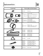
Page 39: ... N A Fuel Filter LZ 60 w Kawasaki N A Oil Filter LZ 48 KH 12 050 01 S Oil Filter LZ 54 LZ 60 w Kohler N A Oil Filter LZ 60 w Kawasaki 954 04323 Deck Belt LZ 48 754 04327 Deck Belt LZ 54 754 04319 Deck Belt LZ 60 954 04326 PTO Belt LZ 48 754 04328 PTO Belt LZ 54 754 04296 PTO Belt LZ 60 954 04320 Drive Belt 02005017 Hi Lift Blade 17 0 LZ 48 02005017 X Xtreme Mowing Blade LZ 48 02005018 Hi Lift Blad...

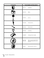
Page 40: ...eck Wheel 925 1707D Battery 751 12754 Gas Cap 946 04840 Throttle Control 946 04812 Choke Control 925 2054A Ignition Key 01006693P Discharge Chute Assembly 634 04749 Wheel Assembly LZ 48 24 x 9 5 12 634 04734 Wheel Assembly LZ 54 LZ 60 24 x 12 12 02002821 Wheel Assembly 13 x 6 50 6 ...

Page 41: ...Attachments Accessories 10 41 Part No Part 59A30033150 Power Assist Triple Bagger 59A30036150 72 Snow Blade 59A30035150 Electric Deck Lift 490 850 0005 Blade Removal Tool 490 850 0008 Oil Siphon ...

Page 42: ...at cause the failure of a warranted part to be identical in all material respects to that part as described in MTD Consumer Group Inc s application for certification The warranty period begins on the date the outdoor equipment engine is delivered to an ultimate purchaser or first placed into service The warranty period is two years Subject to certain conditions and exclusions as stated below the w...

Page 43: ...till eligible for warranty coverage Further the coverage under this warranty extends only to parts that were present on the off road engine and equipment purchased The following emission warranty parts are covered if applicable 1 Fuel Metering System Cold start enrichment system soft choke Carburetor and internal parts or fuel injection system Fuel pump Fuel tank 2 Air Induction System Air cleaner...

Page 44: ...ual will void your warranty as to any resulting damage In addition Cub Cadet may deny warranty coverage if the hour meter or any part thereof is altered modified disconnected or otherwise tampered with HOW TO OBTAIN SERVICE Warranty service is available WITH PROOF OF PURCHASE AND APPLICABLE MAINTENANCE RECORDS through your local authorized service dealer To locate the dealer in your area In the U ...

Reviews: