


RZT-S Zero
86
C.
If all of the controllers read battery voltage, the
pre-charge voltage is reaching the controllers, but
this does not mean that the master relay is func-
tional. To test the master relay:
1.
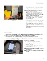
Set a DMM to measure DC volts.
2.
Place the negative probe in pin 3 of the breakout
adapter. See Figure 5.55.
3.
Place the positive probe in pin 4 of the breakout
adapter.
4.
While sitting in the seat with key switch in the “ON”
position, depress the start button while watching the
DMM.
•
If the DMM reads battery voltage, the contactor
assembly is faulty, replace the control panel.
•
If the VCM reads 0 volts, the fault is either the
VCM or the harness. Test the VCMs output to
determine if the fault is in the VCM or the har-
ness.
5.
Remove the VCM by following the procedures
described in the Vehicle Control Module (VCM) sec-
tion of this chapter.
6.
Install the harness break out adapters.
7.
Place the positive probe in pin 11 of the 12 pin
breakout adapter.
8.
Place the negative probe in pin 10 of the 12 pin
breakout adapter.
9.
While sitting in the seat with key switch in the “ON”
position, depress the start button while watching the
DMM.
•
The DMM should read battery voltage. If the
DMM measures 0 volts, the VCM is faulty.
•
If the DMM reads battery voltage, there is a
fault in the harness.
Figure 5.55
12 pin adapter
Figure 5.56
12 pin adapter
Summary of Contents for RZT-S Zero
Page 2: ......
Page 42: ...RZT S Zero 38 ...
Page 112: ...RZT S Zero 108 ...
Page 154: ...NOTES ...
Page 155: ......
Page 156: ...MTD Products Inc Product Training and Education Department FORM NUMBER 769 08008 02 05 2013 ...


