background image

16

6

Maintaining 

Your Snow 

Thrower

WARNING

Before lubricating, 
repairing or 
inspecting, disengage 
all controls and stop 
engine.  Wait until all 
moving parts have 
come to a complete 
stop. Remove the 
safety key to prevent 
unintended firing of 
the engine.

IMPORTANT

Avoid oil spillage on 
rubber friction wheel 
and aluminum drive 
plate.

Figure 6-1

Figure 6-2

Lubrication

Drive and Shifting Mechanism

At least once a season or after every 25 hours of opera-
tion, remove rear cover. Lubricate any chains, sprockets, 
gears, bearings, shafts, and the shifting mechanism at 
least once a season. Use engine oil or a spray lubricant. 
Refer to Figure 6-1.

IMPORTANT: 

Keep all grease and oil off the rubber 

friction wheel and drive plate.

Wheels

At least once a season, remove wheels. Clean and coat 
the axles with a multipurpose automotive grease before 
reinstalling wheels.

Auger Shaft

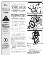
At least once a season, remove the shear pins on auger 
shaft. Spray lubricant inside shaft, around the spacers. 
Also lubricate the flange bearings found at either end of 
the shaft. See Figure 6-2. 

Augers

•  The augers are secured to the spiral shaft with shear 

pins and cotter pins. If the auger should strike a 
foreign object or ice jam, the snow thrower is designed 
so that the pins may shear. See Figure 6-2.

•  If the augers will not turn, check to see if the pins have 

sheared. Replacement shear pins have been provided 
with the snow thrower. When replacing pins, spray an 
oil lubricant into shaft before inserting new pins.

Shave Plate and Skid Shoes

The shave plate and skid shoes on the bottom of the 
snow thrower are subject to wear. They should be 
checked periodically and replaced when necessary.
To remove skid shoes:
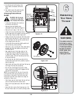
1.  Remove the carriage bolts (and washers if 

equipped)and hex flange nuts which secure the skid 
shoes to the snow thrower. 

2.  Reassemble new skid shoes with previously removed 

hardware. Refer to Figure 6-3.

To remove shave plate:
1.  Remove the carriage bolts and hex nuts which attach 

it and the skid shoes to the snow thrower housing. 

2.  Reassemble new shave plate, making sure heads of 

carriage bolts are to the inside of housing. Tighten 
securely. 

Replacing Belts

To remove and replace either the auger belt or the drive 
belt, follow the steps below and then proceed to the 
specific steps listed under respective sub-headings.

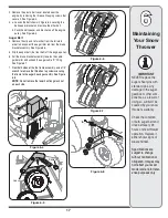
1.  Disconnect the chute crank assembly at the discharge 

chute end by removing the hairpin clip and the flat 
washer. See Figure 6-8.

Figure 6-3

Shear Pin

Vent Plug

Grease

Fitting (optional)

Bearing

Spacers

Cotter Pin

Auger Shaft

Engine

Refer to the separate engine manual packed with your 
unit for all engine maintenance and lubrication instruc-
tions.

Friction 
Wheel

Drive 
Plate

Gear 
(Hex) 
Shaft

Summary of Contents for OEM-390-679

Page 1: ...e Troubleshooting Parts Lists Warranty 60 Ottawa Street South KITCHENER ONTARIO N2G 4J1 PRINTED IN U S A IMPORTANT READ SAFETY RULES AND INSTRUCTIONS CAREFULLY BEFORE OPERATION OPERATOR S MANUAL 06 10 08 769 04103 28 30 33 45 Two Stage Snow Throwers ...

Page 2: ...Thrower 10 MakingAdjustments 14 Maintaining Your Snow Thrower 16 Off Season Storage 20 Trouble Shooting 21 Warranty 22 Illustrated Parts Lists 24 If you have difficulty assembling this product or have any questions regarding the controls operation or maintenance of this unit you can seek help from the experts Choose from the options below 1 Visit www cubcadet ca cubcadet for many useful suggestion...

Page 3: ...es before refueling WARNING CARBON MONOXIDE Never run an engine indoors or in a poorly ventilated area Engine exhaust contains carbon monoxide an odorless and deadly gas WARNING ELECTRICAL SHOCK Do not use the engine s electric starter in the rain 1 Safety Symbols This page depicts and describes safety symbols that may appear on this product Read understand and follow all instructions on the machi...

Page 4: ...asoline is spilled on yourself or your clothes which can ignite Wash your skin and change clothes immediately a Use only an approved gasoline container b Extinguish all cigarettes cigars pipes and other sources of ignition c Never fuel machine indoors d Never remove gas cap or add fuel while the engine is hot or running e Allow engine to cool at least two minutes before refuel ing f Never over fil...

Page 5: ...or inspecting machine disengage all control levers and stop the engine Wait until the auger impeller come to a complete stop Disconnect the spark plug wire and ground against the engine to prevent unintended starting 3 Check bolts and screws for proper tightness at frequent intervals to keep the machine in safe working condition Also visually inspect machine for any damage 4 Do not change the engi...

Page 6: ... Figure 3 2 Raise the upper handle assembly until it locks over the lower handle See Figure 3 1 Secure the upper handle and lower handle with the handle knobs washers and carriage bolts previously removed Tighten the handle knobs already in place on the upper holes and secure the handles firmly Attaching Chute Crank Remove the hairpin clip from the upper chute crank and slide the upper chute crank...

Page 7: ...crank support bracket can be adjusted so the spiral on the chute crank fully engages the teeth on the chute assembly Refer to the Adjustment Section Attaching the Shift Rod Align the upper and lower shift rods then slide the shift rod connector down over the end of the lower shift rod Tap the connector until the lower rod is completely through the connector See Figure 3 6 NOTE If the connector is ...

Page 8: ... to follow these instruc tions may cause damage to the snow thrower Wheel Drive Control Shift Lever Perform the following test to determine need for adjust ment Move the shift lever into sixth 6 position See Figure 4 1 With the drive control released see Figure 3 11A push the snow thrower forward then pull it back The machine should move freely Engage the drive control and attempt to move the mach...

Page 9: ...ntrol is released and in the disengaged up position see Figure 3 11B the cable should have very little slack but should NOT be tight See Figure 3 12 WARNING Do not over tighten the cable Over tightening may prevent the auger from disengaging and compro mise the safety of the snow thrower In a well ventilated area start the snow thrower engine as instructed on page 12 While standing in the operator...

Page 10: ...into the engine s carburetor to aid in cold weather starting Oil Fill Engine oil level can be checked and oil added through the oil fill Safety Key The safety key must be pushed in place in order for the engine to start Pull the safety key out to prevent unauthor ized use of equipment Rocker Switch The rocker switch is used to stop the engine The switch must be in the ON position in order to start...

Page 11: ...bstitute for proper cold weather outerwear for the operator s hands It is recommended that the snow thrower operator wear gloves mittens to avoid extremities of winter while operating this equipment 5 2 42 2 6 42 Two Way Chute Control This two way control lever is meant to control the distance of snow discharge from the chute Tilt the lever forward or rearward to adjust the distance snow will be t...

Page 12: ...ters quickly rotate the choke control back to FULL and then slowly into the OFF position again 5 When disconnecting the extension cord always unplug the end at the three prong wall outlet before unplugging the opposite end from the snow thrower Recoil Starter 1 Grasp the recoil starter handle and slowly pull the rope out At the point where it becomes slightly harder to pull the rope slowly allow t...

Page 13: ...urrounding areas may exceed 150 F 65 C Avoid these areas 1 If possible remove snow immediately after it falls 2 Discharge snow downwind whenever possible 3 Slightly overlap each previous path 4 Set the skid shoes 1 4 below the shave plate for normal usage Adjust them upward for hard packed snow and downward when using on gravel or crushed rock General Recommendations 1 Always observe safety rules ...

Page 14: ...the ferrule lines up with the hole from which it was earlier removed See Figure 5 1 5 From the direction noted earlier insert the ferrule into the proper hole 6 Reinstall the washer and the internal cotter pin Drive Control WARNING Run the engine com pletely dry of gasoline before tipping snowthrower Refer to the Final Adjustment section of the Set Up instructions to adjust the drive control To fu...

Page 15: ... which fasten the skid shoe to the auger housing 2 Raise or lower the skid shoe to desired position 3 Retighten the hex nuts loosened earlier NOTE Make certain the bottom surface of skid shoe is flat against the ground to avoid uneven wear 4 Repeat on the other side of the snow thrower Auger Control Refer to instructions on page 9 to adjust the auger control Make certain to check for correct adjus...

Page 16: ...y shear See Figure 6 2 If the augers will not turn check to see if the pins have sheared Replacement shear pins have been provided with the snow thrower When replacing pins spray an oil lubricant into shaft before inserting new pins Shave Plate and Skid Shoes The shave plate and skid shoes on the bottom of the snow thrower are subject to wear They should be checked periodically and replaced when n...

Page 17: ...hook the auger cable Z fitting See Figure 6 7 7 From both sides of the the frame assembly use a 1 2 wrench to remove the three hex tap screws securing the frame to the auger housing assembly See Figure 6 8 NOTE Do not remove the lower hex flange lock nut on each side IMPORTANT NEVER replace the auger shear pins with standard pins Any damage to the auger gearbox or other com ponents as a result of ...

Page 18: ...r input shaft and push the pulley and adapter onto the input shaft Refer to Figure 6 10 13 Slide the washer onto the hex screw removed earlier and apply Loctite 262 to the threads of the hex screw 14 Insert the hex screw through the pulley assembly and into the threads of the input shaft Torque the hex screw to 250 325 in lbs to secure the auger pulley assembly on the input shaft If also replacing...

Page 19: ...ing and through the friction wheel assembly Insert the hex shaft through the sprocket and the spacer Make certain that the chain engages both the large and the small sprocket NOTE If the sprocket fell from the snow thrower while removing the hex shaft align sprocket on chain place the sprocket on the hex shaft Position the hex hub of the sprocket toward the friction wheel when sliding the sprocket...

Page 20: ...repare for storage as instructed in the separate engine manual packed with your snow thrower Clean snow thrower thoroughly Lubricate as instructed in the Maintenance section of this manual Refer to engine manual for correct engine storage instructions Store the snow thrower in a clean dry area When storing any type of power equipment in a poorly ventilated or metal storage shed care should be take...

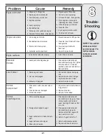
Page 21: ...nter 1 Carburetor not adjusted properly Loss of power 1 Connect and tighten spark plug wire 2 Remove ice and snow from gas cap Be certain vent is clear 3 Contact Service Center 1 Spark plug wire loose 2 Gas cap vent plugged 3 Exhaust port plugged Unit fails to propel itself 1 Adjust drive control cable Refer to Adjustments 2 Replace drive belt 3 Replace friciton wheel 1 Drive control cable in need...

Page 22: ...de sharpening tune ups brake adjustments clutch adjustments deck adjustments and normal deterioration of the exterior finish due to use or exposure d Service completed by someone other than an authorized service dealer e MTD does not extend any warranty for products sold or exported outside of Canada including possessions and territories f Replacement parts that are not genuine MTD parts g Transpo...

Page 23: ...23 NOTES For parts and or accessories refer to customer support on page 2 Adressez vous au Service après vente à la page 2 pour ce qui concerne les pièces et ou accessoires ...

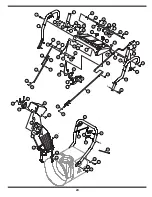
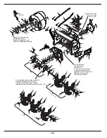
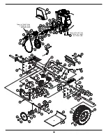
Page 24: ... 56 49 63 44 43 52 58 21 5 26 33 38 20 19 34 3 19 32 21 2 39 7 36 14 1 41 19 19 35 29 31 19 68 47 60 61 2 64 65 71 4 59 51 28 45 57 40 48 31 62 69 66 67 24 47 37 27 15 16 10 18 47 68 53 54 69 16 55 46 9 8 23 28 11 28 12 13 30 72 73 22 ...

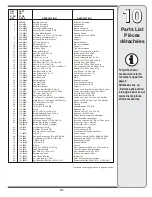
Page 25: ...89A Upper Handle LH Guidon supérieur CG 39 749 0990A Upper Handle RH Guidon supérieur CD 40 749 0991 Lower Handle Guidon supérieur 41 750 0963 Connector Shift Rod Raccord tige de changement de la vitesse 42 684 0102A Handle Panel Support Ass y Ensemble de suppport de panneau 43 710 0276 Carriage Bolt 5 16 18 x 1 00 Lg Boulon ordinaire de 5 16 18 x 1 00 po de lg 44 710 0458 Carriage Bolt 5 16 18 x ...

Page 26: ...tly above asphalt Set to maximum for gravel driveways La plaque de râclage doit être légèrement au dessus du goudron Réglez la au maximum en cas d allées gravillonnées When rebuilding gear box fill one housing half completely with grease 838 0168 Pour remonter la boîte d engrenages remplissez complètement une moitié avec de la graisse no 838 0168 Torque to 20 30 in lbs Serrez à un couple de 20 30 ...

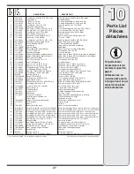
Page 27: ... 10 0 DE 35 738 0281 Shoulder Scr 625 Dia x 170 Vis à épaulement dia 0 625 x 0 170 po 36 784 0385B Auger Idler Bracket Support de tension de la tarière 37 736 0174 Wave Washer 625 ID x 885 OD x 015 Rondelle ondulée 0 625 DI x 0 885 DE x 0 015 38 710 0451 Carriage Bolt 5 16 18 x 75 Boulon ordinaire 5 16 18 x 0 75 39 710 04606 Screw 5 16 18 x 43 w stud Vis 5 16 18 x 0 43 avec clou 40 747 0980A Auger...

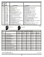
Page 28: ...8 04067A Pulley Adapter 75 Dia w pins Adaptateur de poulie 0 75 diam avec attaches 84 710 0376 Hex Hd Cap Scr 5 16 18 x 1 0 Gr 5 Vis à tête hex 5 15 18 x 1 0 Qual 5 85 710 0276 Carriage Bolt 5 16 18 x 1 00 Lg Boulon ordinaire de 5 16 18 x 1 00 po de lg 31A 8012 6 9 08 AUGER HOUSING COMPONENTS COMPOSANTS DU LOGEMENT DES TARIÈRES SIZE TAILLE DESCRIPTION AUGER HSG LOGEMENT DES TARIÈRES LH AUGERS TARI...

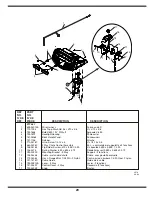
Page 29: ... 684 04230 2 Way Chute Control Assembly Ens commande de la goulotte à 2 fonctions 9 738 04185 Flg Shlder Sscrew 310 x 995 1 4 20 Vis épaulée 0 390 x 0 995 1 4 20 10 736 0413 Spring Washer 390 x 625 x 012 Rondelle ressort 0 390 x 0 625 x 0 012 11 790 00200 Mounting Bracket 2 Way Support 2 fonctions 12 746 04338 Cable w standard chute Câble avec goulotte ordinaire 13 712 04064 Hex L Flanged Nut 1 4 ...

Page 30: ...43 43 24 71 24 18 66 3 63 40 38 69 48 31 10 63 6 64 17 62 7 37 39 33 65 16 57 30 45 55 47 76 61 75 34 34 5 68 17 Torque to 325 450 in lbs Serrez à un couple de 325 450 po lb Torque to 325 550 in lbs Serrez à un couple de 325 550 po lb 29 B 94 29 81 12 14 90 49 100 28 79 89 44 78 99 83 88 85 77 93 87 15 84 22 97 46 98 95 91 82 92 80 86 ...

Page 31: ...0 75 32 712 0717 Nut Insert 3 8 16 UNC Écrou inserer 3 8 16 UNC 33 713 0284 41 Chain 1 2 pitch x 36 links Endless Chaîne no 41 pas de 1 2 po x 36 maillons 34 713 0286 420 Chain 1 2 pitch x 40 links Endless Chaîne no 420 pas de 1 2 po x 40 maillons 35 713 04015 10T Sprocket 41 x 500 Pignon 10 dents 36 714 0135 Woodruff Key Clavette 37 714 0104 Int Cotter Pin 5 16 DIA Goupille fendue 5 16 DIA 38 716...

Page 32: ...5 16 24 x 1 5 Lg Gr 5 Vis à tête hexagonal 5 16 24 x 1 5 po de lg Qual 5 82 710 0654A Hex Wash HD Tap Scr 3 8 16 x 1 00 Vis autotaraudée 3 8 16 x 1 00 83 710 0627 Hex Hd Cap Scr 5 16 24 x 0 75 Gr 5 Boulon hex 5 16 24 x 0 75 Qual 5 84 714 0118 Square Key 1 4 x 1 4 x 1 50 Lg Clavette 1 4 x 1 4 x 1 50 po de lg 85 790 00167A Belt Keeper Bracket Support du protecteur de la courroie 86 731 2531 Belt Cov...

Page 33: ...33 NOTES For parts and or accessories refer to customer support on page 2 Adressez vous au Service après vente à la page 2 pour ce qui concerne les pièces et ou accessoires ...

Page 34: ...23 NOTES For parts and or accessories refer to customer support on page 2 Adressez vous au Service après vente à la page 2 pour ce qui concerne les pièces et ou accessoires ...

Page 35: ...pe et la détérioration normale de la finition du fait de l utilisation de la machine ou de son exposition aux intempéries d L entretien ou les réparations effectués par quiconque autre qu une station technique agréée e MTD ne garantit pas les produits vendus ou exportés du Canada de ses possessions et territoires f Les pièces de rechange si elles ne sont pas des pièces MTD authentiques g Les frais...

Page 36: ...l réglé Moteur surchauffe Perte de puissance 1 Branchez et serrez le fil de la bougie 2 Dégagez la glace et la neige du chapeau Assurez vous de la propreté d aération 3 Adressez vous à une station technique 1 Fil de la bougie desserré 2 Chapeau d échappement d aération bouché 3 Le port déchappement est bouché La souffleuse n avance pas 1 Réglez le câble d entraînement Voir le Réglages 2 Remplacez ...

Page 37: ...30 jours préparez le de la façon selon les instructions fournies dans la notice d utilisation du moteur qui accompagne votre souffleuse Consultez la notice d utilisation du moteur Enlevez tout les débris sur l extérieur de la souffle use Suivez les renseignements de lubrification à la page 16 Entreposez la souffleuse dans un endroit sec et propre Prenez soin avant de remiser une machine à moteur d...

Page 38: ...a roue de frottement entre l arbre de l essieu et l arbre d entraînement Enlevez les quatre vis de l ensemble de la roue de frottement et retirez le caoutchouc de la roue de frottement de la plaque de serrage Voir la Figure 6 13 Jetez le vieux caoutchouc Installez le nouveau caoutchouc de la roue de frotte ment sur la roue de frottement Serrez les quatre vis l une après l autre dans l ordre avec u...

Page 39: ...on Si vous remplacez aussi la courroie d entraînement suivez les instructions du paragraphe Courroie d entraînement Sinon procédez dans le sens inverse au démontage REMARQUE N oubliez pas d enlever la cale en bois qui bloque la turbine Réglage correct Quand la commande de la tarière n est pas enclenchée la surface supérieure de la cour roie neuve doit être de niveau avec la diamètre extérieur de l...

Page 40: ...e ment avec des boulons ordinaires Les dégâts à l ensemble de la vis sans fin ou à d autres composants en résultant ne seront pas couverts par la garantie de votre souffleuse Vérifiez l état de la courroie des tarières et de la courroie d entraînement toutes les 25 heures d utilisation de la souffleuse Remplacez toute courroie qui paraît usée Les caractéristiques techniques peuvent être modifiées ...

Page 41: ...ont fournies Vaporisez un lubrifiant à base d huile sur l arbre avant d installer les goupilles Lame et patins La lame plate et les patins sont installés sous la souffleuse et ils risquent de s user Vérifiez les régulièrement et remplacez les au besoin Pour démonter les patins 1 Enlevez les boulons ordinaires et la rondelle plate le cas échéant et les contre écrous à embase qui les maintiennent su...

Page 42: ...ez ou abaissez le patin à la position voulue 3 Serrez les écrous à six pans desserrés plus tôt REMARQUE Vérifiez que toute la surface inférieure des patins est de niveau et en contact avec le sol pour éviter leur usure inégale 4 Répétez l ajustement sur l autre patin Commande de la tarière Consultez les instructions à la page 9 pour ajuster la commande de la tarière Vérifiez bien que l ajustement ...

Page 43: ...t Voir la Figure 5 1 5 Installez la virole dans le trou approprié dans le sens noté précédemment 6 Ré installez la rondelle et la goupille fendue interne Commande de l entraînement des roues AVERTISSEMENT Laissez tourner le moteur jusqu à ce qu il tombe en panne d essence avant de faire basculer la souffleuse Consultez la partie concernant le Réglage final dans le chapitre Instructions de Montage ...

Page 44: ...eur d orienter la goulotte sans cesser de projeter la neige 3 Débrayez la commande de la tarière le mécanisme de blocage maintient la tarière engagée jusqu à ce que la commande de la transmission soit débrayée 4 Lâchez la commande de la transmission pour arrêter la tarière et les roues Pour arrêter la tarière les deux poignées doivent être débrayées Conseils d utilisation REMARQUE Laissez le moteu...

Page 45: ...émarreur électrique sur certains modèles 1 Vérifiez que le câblage de votre maison comporte trois fils reliés à la terre Si vous n êtes pas certain renseignez vous auprès d un électricien AVERTISSEMENT Ce démarreur en option est équipé d un fil et d une prise électrique à trois fils et il est conçu pour fonctionner sur un courant de 120 volts C A Il doit toujours être relié à la terre pour éviter ...

Page 46: ...levier de vitesses pour changer de vitesse ou de sens de déplacement sans avoir au préalable débrayé la commande de la transmission et avoir complètement arrêté la souffleuse Ceci pourrait causer l usure prématurée de la transmis sion de la souffleuse Commutateur de chauffage des poignées le cas échéant Il se trouve sur la droite du tableau de commande de la souffleuse Pour chauffer les poignées p...

Page 47: ...1 R Levier de vitesses Il se trouve au milieu du tableau de bord et sert à choisir la vitesse et la direction de déplacement Il peut être placé à l une quelconque de huit positions IMPORTANT Débrayez toujours la com mande de l entraînement des roues avant de changer de vitesse Marche avant La souffleuse a six marches avant F La position 1 est la plus lente et la position 6 la plus rapide Marche ar...

Page 48: ...essort sur l extrémité du câble de la tarière du support de l actionneur Voir la Figure 3 12 Poussez le raccord du câble dans l extrémité du ressort pour dégager l écrou de blocage Voir la Figure 3 13 Vissez l écrou de blocage vers l extérieur en descendant sur le raccord de trois tours complets pour donner plus de jeu au câble et raccrochez le ressort sur le support Répétez le test pour vérifier ...

Page 49: ...11A poussez la souffleuse puis tirez la La machine doit bouger facilement Embrayez la commande de l entraînement et essayez de déplacer la souffleuse vers l avant ou vers l arrière Vous devez sentir une résistance Placez le levier de vitesses à la position de marche ar rière rapide R2 et répétez les deux tests précédents Si la machine résiste au mouvement quand le levier de vitesses est déplacé de...

Page 50: ... des tiges sur l extrémité de la tige du levier de vitesses inférieure Tapez sur le raccord jusqu à ce qu il passe bien à travers la tige du levier de vitesses inférieure Voir la Figure 3 6 REMARQUE Si le raccord n est pas bien installé la tige du levier de vitesses pivotera et il sera impossible de changer de vitesse ou de direction REMARQUE S il n est pas possible d utiliser toutes les vitesses ...

Page 51: ...périeur Voir la Figure 3 2 Relevez le guidon supérieur jusqu à ce qu il s emboîte sur le guidon inférieur See Figure 3 1 Attachez les guidons supérieur et inférieur avec les boutons rondelles et les boulons ordinaires enlevés précédemment Serrez les boutons déjà en place sur les trous supérieurs et fixez les guidons fermement Montage de la manivelle de la goulotte Dégagez la goupille fendue de l e...

Page 52: ...intenez la machine en bon état de marche Examinez soigneusement la machine pour vous assurer qu elle n est pas endommagée 4 Ne modifiez pas le réglage du régulateur et ne laissez pas le moteur s emballer ce qui peut être dangereux 5 Les plaques de raclage et les patins de la souffleuse s usent avec l usage Par mesure de sécurité vérifiez souvent tous les composants et remplacez les par des pièces ...

Page 53: ...dant au moins deux minutes avant de faire le plein f Ne faites jamais déborder le réservoir Laissez un espace d un demi pouce environ pour permettre l expansion du carburant g Resserrez bien le capuchon d essence h En cas de débordement essuyez toute éclaboussure sur le moteur et la machine Déplacez la machine et attendez 5 minutes avant de la remettre en marche i Ne remisez jamais la machine ou l...

Page 54: ...utes avant de refaire le plein AVERTISSEMENT MONOXYDE DE CARBONE Ne faites jamais fonctionner un moteur à l intérieur ou dans un bâtiment mal ventilé Les gaz d échappement contiennent du monoxyde de carbone un gaz inodore et mortel 1 Symboles de sécurité Cette page illustre et explique les symboles de sécurité qui peuvent se trouver sur cette machine Veuillez lire et suivre toutes les instructions...

Page 55: ...uffleuse 10 Réglages 14 Régime d entretien 16 Remisage hors saison 20 Dépannage 21 Garantie 22 Pièces détachées voir la page 24 de la version anglaise de cette notice d utilisation Si l assemblage de cette machine vous pose des problèmes ou pour toute question concernant les commandes le fonctionnement ou l entretien de la machine les spécialistes sont à votre disposition Choisissez l une des opti...

Page 56: ...Fonctionnement Réglages Entretien Dépannage Listes des pièces détachées Garantie NOTICE D UTILISATION IMPORTANT LISEZ ATTENTIVEMENT LES RÉGLES DE SÉCURITÉ ET LES INSTRUCTIONS AVANT DE METTRE EN MARCHE LA MACHINE 06 10 08 769 04103 Souffleuses à neige à deux phases de 28 po 30 po 33 po et 45 po ...

Reviews: