


Domestic Series 5000 MFD
41
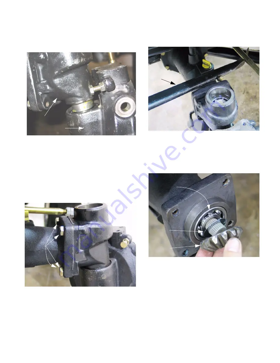
7.9.
The drop axle housing can then be pushed down
off of the kingpin housing with some twisting and
light force. See Figure 7.9.
7.10. Most service that requires the removal of the
drop axle housing is most easily performed by
removing the drop axle housing along with the
kingpin housing.
7.11. To separate the kingpin housing from the axle
housing, loosen all four bolts that secure the two
together using a 16 mm wrench.
See Figure 7.11.
NOTE:
It may be useful to use the head of a
loosened bolt to pry or drive against to loosen
the sealant between the two castings.
Figure 7.9
Kingpin housing
Drop axle housing
Figure 7.11
Bolts
7.12. Support the drop axle housing, and separate it
from the axle housing. See Figure 7.12.
7.13. With the kingpin housing removed, access is
gained to the bevel gear on the end of the axle
shaft, and the bearing that supports the outer
end of the axle shaft. See Figure 7.13.
7.14. The gear and bearing are easily removed.
Figure 7.12
Pry bar
Figure 7.13
14 tooth
bevel gear
Washer
Axle bearing
(outboard)
www.mymowerparts.com
K&T Saw Shop 606-678-9623 or 606-561-4983


