


Assembly & Set-Up
2
5
Thank you for purchasing your new equipment. It was carefully engineered
to provide excellent performance when properly operated and maintained.
Please read this entire manual prior to operating the equipment. It instructs
you how to safely and easily set up, operate and maintain your machine.
Please be sure that you, and any other persons who will operate the
machine, carefully follow the recommended safety practices at all times.
Failure to do so could result in personal injury or property damage.
All information in this manual is relative to the most recent product
information available at the time of printing. Review this manual frequently
to familiarize yourself with the machine, its features and operation. Please
be aware that this Operator’s Manual may cover a range of product
specifications for various models. Characteristics and features discussed
and/or illustrated in this manual may not be applicable to all models. The
manufacturer reserves the right to change product specifications, designs
and equipment without notice and without incurring obligation.
The engine manufacturer is responsible for all engine-related issues with
regards to performance, power-rating, specifications, warranty and service.
Please refer to the engine manufacturer’s Owner’s/Operator’s Manual,
packed separately with your machine, for more information.
If you have any problems or questions concerning the machine, phone your
local authorized service dealer or contact us directly. We want to ensure
your complete satisfaction at all times.
Throughout this manual, all references to
right
and
left
side of the machine
are observed from the operating position.
Thank You
NOTE:
This Operator’s Manual covers several
models. Features may vary by model. Not all
features in this manual are applicable to all
models and the model depicted may differ from
yours.
Tools Required
•
Adjustable Wrench or Socket Set
•
Needle Nose Pliers
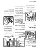
Chute Assembly
Overhead Chute Control
(with Flex Shaft and Steel Chute)
Flex Shaft
Figure 2-1
Handle Assembly
1.
Cut cable ties securing chute control rod
or flex shaft to lower handle (if applicable)
and set aside.
NOTE:
If your unit is equipped with a
cable tie securing the control cables to the
engine do not cut the cable tie.
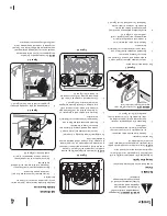
2.
Loosen the top two lock nuts (a) securing
the upper and lower handle and remove
the two carriage screws (b) from the lower
handle and set aside as shown in Figure
2-2.
3.
Place shift lever in Forward-6 position
(if equipped).
(a)
(a)
(a)
(a)
(b)
(b)
Figure 2-2
4.
Observe lower rear area of equipment to
be sure both cables are aligned and seated
properly in roller guides. See Figure 2-3.
NOTE:
On select units, chute-pitch control
cables will be routed under the engine on the
left side and will not use roller guides.
Figure 2-3
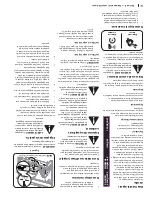
5.
Pull up on the upper handle, align the
upper handle with the lower handle. See
Figure 2-4.
6.
Reattach the two carriage screws and lock
nuts removed earlier as shown in Figure
2-2.
7.
Finish securing the handle by tightening
the top two lock nuts loosened earlier.
Remove and discard any rubber bands, if
present. They are for packaging purposes
only
.
Figure 2-4
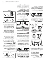
Chute Clean-Out Tool
The chute clean-out tool is fastened to the top
of the auger housing with a mounting clip. See
Figure 2-5.
Figure 2-5


