background image

 Installation  

21 


2.3.2.2 Install Two Managed Switches in a Rack Using the Combine 

Kit 

To install two sets of the 8.5-inch Managed Switch in a single rack space, you need the 19-inch 
rack-mount kit as well as the combine kit, supplied with the switch. Also follow the procedures listed 
below for step-by-step instructions to install your switches in this rack space:  


Step 1. 

On the switch that will be mounted on the left side of the rack space, do the following: 


1.1.

 Refer to Section 2.3.2.1 to attach the supplied regular mounting bracket to the left side 

of this switch.  

1.2. 

Insert the screws provided in the rack-mount kit through the bracket and into the 

bracket mounting holes in the switches. 

1.3. 

Tighten the screws with the screwdriver to secure the bracket. 

1.4.

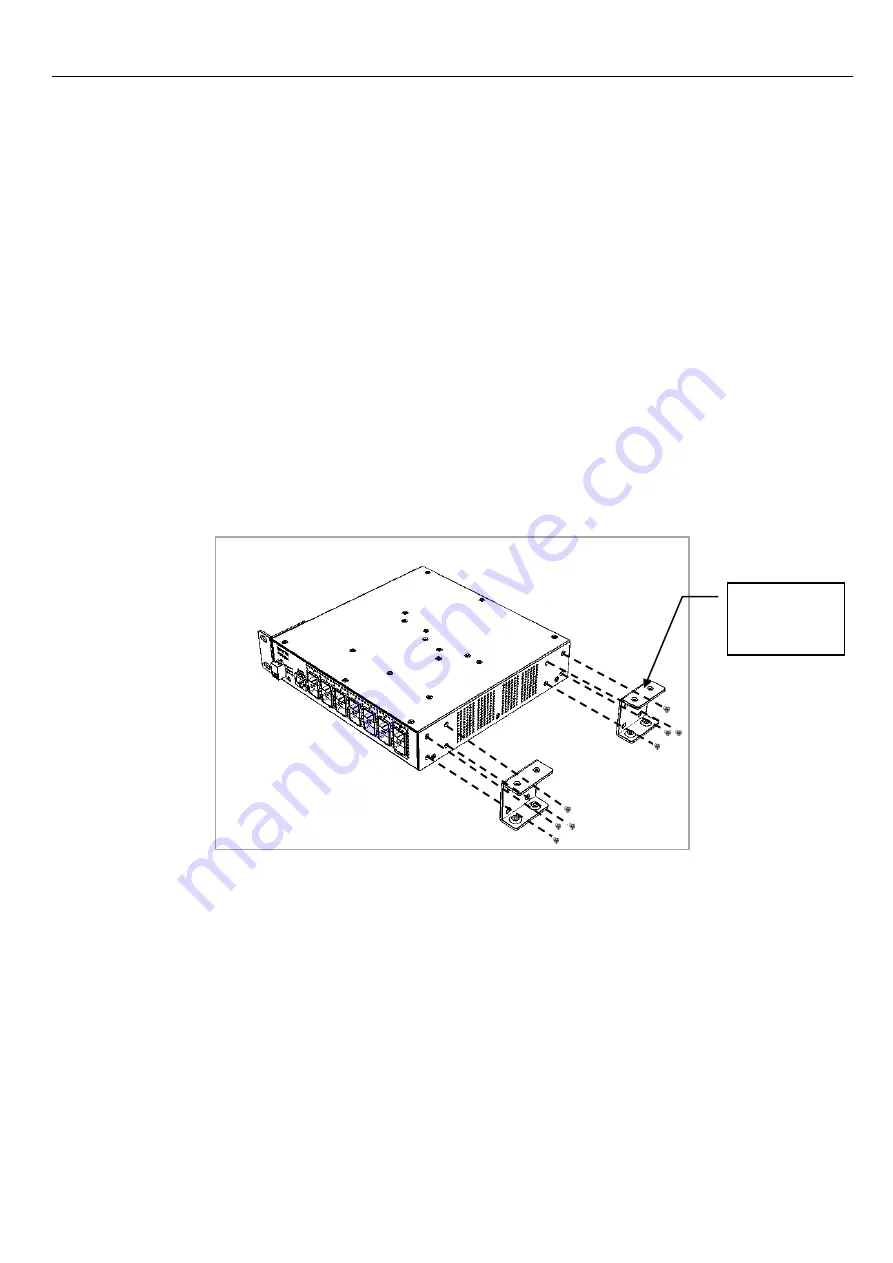
 On the right side of the switch, attach


one 

-shaped fixed piece


by inserting the 

screws provided in


the combine kit through this fixed piece


and into the mounting 

holes in the switch. (See Figure 2-2)  

1.5. 

Repeat the same manners as we had mentioned in Step 1.4 to install another 

-

shaped fixed piece on the same side of this switch. (See Figure 2-2)


1.6. 

Tighten the screws with the screwdriver to secure each middle mount to the right side 

of the switch. 


Step 2. 

On the other switch that will be mounted on the right side of the rack space, do the 

following: 

2.1.

 Also refer to Section 2.3.2.1 to attach the supplied regular mounting bracket to the 

right side of this switch. 

2.2. 

Insert the screws provided in the rack-mount kit through the bracket and into the 

bracket mounting holes in the switches. 

2.3. 

Tighten the screws with the screwdriver to secure the bracket. 

Figure 2-2. Install the 

-shaped fixed pieces for two-switch mounting 

-shaped 

fixed piece 

Summary of Contents for FOS-5112

Page 1: ...FOS 5112 8 port 100 1000Base X SFP 4 port 1G 10GBase R SFP L2 Managed Fiber Switch User s Guide Version 1 0...

Page 2: ...n of this equipment in a residential area is likely to cause harmful interference in which case the user will be required to correct the interference at their own expense CE Mark Warning This is a Cla...

Page 3: ...A Tel 1 510 509 0304 Sales Direct Line 1 510 509 0305 E mail cts_us ctsystem com Connection Technology Systems Japan Higobashi Bldg No 3 R201 1 23 13 Edobori Nishi ku Osaka 550 0002 Japan Tel 81 6 645...

Page 4: ...18 2 3 1 Desktop Installation 18 2 3 2 Rack Installation 19 2 3 2 1 Install a Managed Switch in a Rack 19 2 3 2 2 Install Two Managed Switches in a Rack Using the Combine Kit 21 2 3 2 3 Install a Sin...

Page 5: ...v CHAPTER 4 MAINTENANCE 31 4 1 FAULT IDENTIFICATION 31 4 1 1 Local Check 31 4 1 2 Remote Check 32 4 2 HARDWARE REPLACEMENT PROCEDURES 32 4 3 FIRMWARE UPGRADE 32...

Page 6: ...TS FOS 5112 Managed Switch but tell you how to install this Managed Switch with detailed instructions Organization of the Manual Chapter 1 Introduction describes the features of the Managed Switch Cha...

Page 7: ...itch provides high performance store and forward switching capability plus other advanced features such as QoS VLAN Spanning Tree LACP and so on LED indicators located on the front panel ease the user...

Page 8: ...P Rate limit control NTP client Static multicasting IGMP v1 v2 v3 snooping IGMP fast leave query MLD v1 v2 snooping IGMP filtering via filtering profile Multicast channel limitations per port DHCP sno...

Page 9: ...port DHCP Auto Provision via DHCP option 60 43 for firmware and configuration Management Functions Console Telnet SSH CLI Web HTTP HTTPS RADIUS for authentication SNMP v1 v2c v3 and network management...

Page 10: ...the Managed Switch The settings will be back to the factory defaults and restart the system 4 Console Port An asynchronous serial console port supports the RS 232 electrical specification The console...

Page 11: ...Installation 11 6 LEDs Includes Power LED Status LED COM LED and LEDs of Fiber 1 12 ports For more details on LEDs description please refer to Section 1 4 LED Definitions...

Page 12: ...e on the rear panel of the Managed Switch is described below 7 Power module and Connector AC power connection 100 240V 50 60Hz 0 4 0 2A DC power connection 48V 0 4A 8 Ground Screw For more information...

Page 13: ...range Fixed in power module is no longer receiving power or DC output fails Status LED The Managed Switch status is indicated by the Status LED on the front panel of the device LED Color Operation Sta...

Page 14: ...data at the speed of 100Mbps Orange Lit when Fiber 1000Mbps port link is up Rapidly blinking when Fiber port is receiving and transmitting data at the speed of 1000Mbps Slowly blinking in every 1 sec...

Page 15: ...mode fiber module 10km 1000BASE LH Single mode fiber module 30km 50km 1000BASE ZX Single mode fiber module 80km SFP Transceiver SFP Transceiver for 1000BASE SX Multi mode fiber module 550m SFP Transc...

Page 16: ...l be respectively described in detail in the following sections Installation Requirements Checking the Package Contents Installing the Managed Switch Grounding the Managed Switch Powering on the Manag...

Page 17: ...e package contents The package should contain the following items One set of the Managed Switch 19 inch rack mounting kit 1 x Long mounting bracket and 2 x regular mounting brackets Screws Four rubber...

Page 18: ...ct the power cord or the wires to ensure that it is secured to the AC or DC power connector Make sure that there is proper heat dissipation from and adequate ventilation around the switch Do not place...

Page 19: ...ch in a single rack space you need the 19 inch rack mount kit supplied with the switch Just follow the procedures listed below for step by step instructions to install your switch in this rack space S...

Page 20: ...ep 4 Align the mounting holes in the brackets with the desired holes in the rack and insert screws through each bracket and into the rack Step 5 Then tighten the screws with the screwdriver to secure...

Page 21: ...racket 1 4 On the right side of the switch attach one shaped fixed piece by inserting the screws provided in the combine kit through this fixed piece and into the mounting holes in the switch See Figu...

Page 22: ...Figure 2 3 2 6 Tighten the screws with the screwdriver to secure each middle mount to the left side of the switch Step 3 Align the holes of the middle mount described in Step 1 on the left switch wit...

Page 23: ...mounting holes in the regular brackets on both sides the left side of the left switch and the right side of the right switch with the desired holes in the rack and insert the screws through each brack...

Page 24: ...es on the most left side of the bracket you purchase 1 2 Insert the screws provided in the 19 inch rack mount bracket through this bracket and into the bracket mounting holes at the bottom of the swit...

Page 25: ...h the desired holes in the rack and insert the screws through this bracket and into the rack Step 4 Tighten the screws with the screwdriver to secure this bracket with the switch switches to the rack...

Page 26: ...noise due to electromagnetic interference EMI Be sure to install the ground connection from the ground screw to the grounding surface before connecting devices Figure 2 7 Grounding Wiring for FOS 511...

Page 27: ...sa 2 7 Installing and Removing SFP SFP Modules 2 7 1 Installing SFP SFP Modules To connect the fiber transceiver and LC SC cable use the following guidelines 1 Position the SFP SFP transceiver with th...

Page 28: ...tic cable out to release it from the transceiver 3 Hold the handle on the transceiver and pull the transceiver out of the slot 2 8 Connecting the Switch to Console Port The switch supports a secondary...

Page 29: ...agement Users may connect a Terminal or PC running the Terminal Emulation program such as Putty or Tera Term with the following serial console port settings to the Managed Switch console port directly...

Page 30: ...ement is done over the network Once the Managed Switch is available on the network you can login and monitor the status of it through a web browser remotely or locally Web management in the local site...

Page 31: ...s can perform local check by observing LED indicators status or check system setup and configuration through console connection When the whole system fails to function 1 Check Power LED status 2 Check...

Page 32: ...O NOT UNDER ANY CIRCUMSTANCES open and attempt to repair it Failure to observe this warning could result in personal injury or death from electrical shock Failure to observe the above warning will imm...

Page 33: ...18F 6 No 79 Sec 1 Xintai 5th Rd XiZhi Dist New Taipei City 221 Taiwan R O C Tel 886 2 2698 9661 Fax 886 2 2698 9662 Dir Line 886 2 2698 9201 www ctsystem com...

Reviews: